
Device for round trip time measurements

a technology of round trip time and measurement device, applied in the field of wireless communication system, can solve the problems of reducing position accuracy, reducing the accuracy of conventional position location techniques based on signals provided by sps and cellular base stations, and slowing down the “time-to-fix” to unacceptably long time periods

Active Publication Date: 2011-11-03
QUALCOMM INC
View PDF4 Cites 69 Cited by
  • Summary
  • Abstract
  • Description
  • Claims
  • Application Information

AI Technical Summary

Benefits of technology

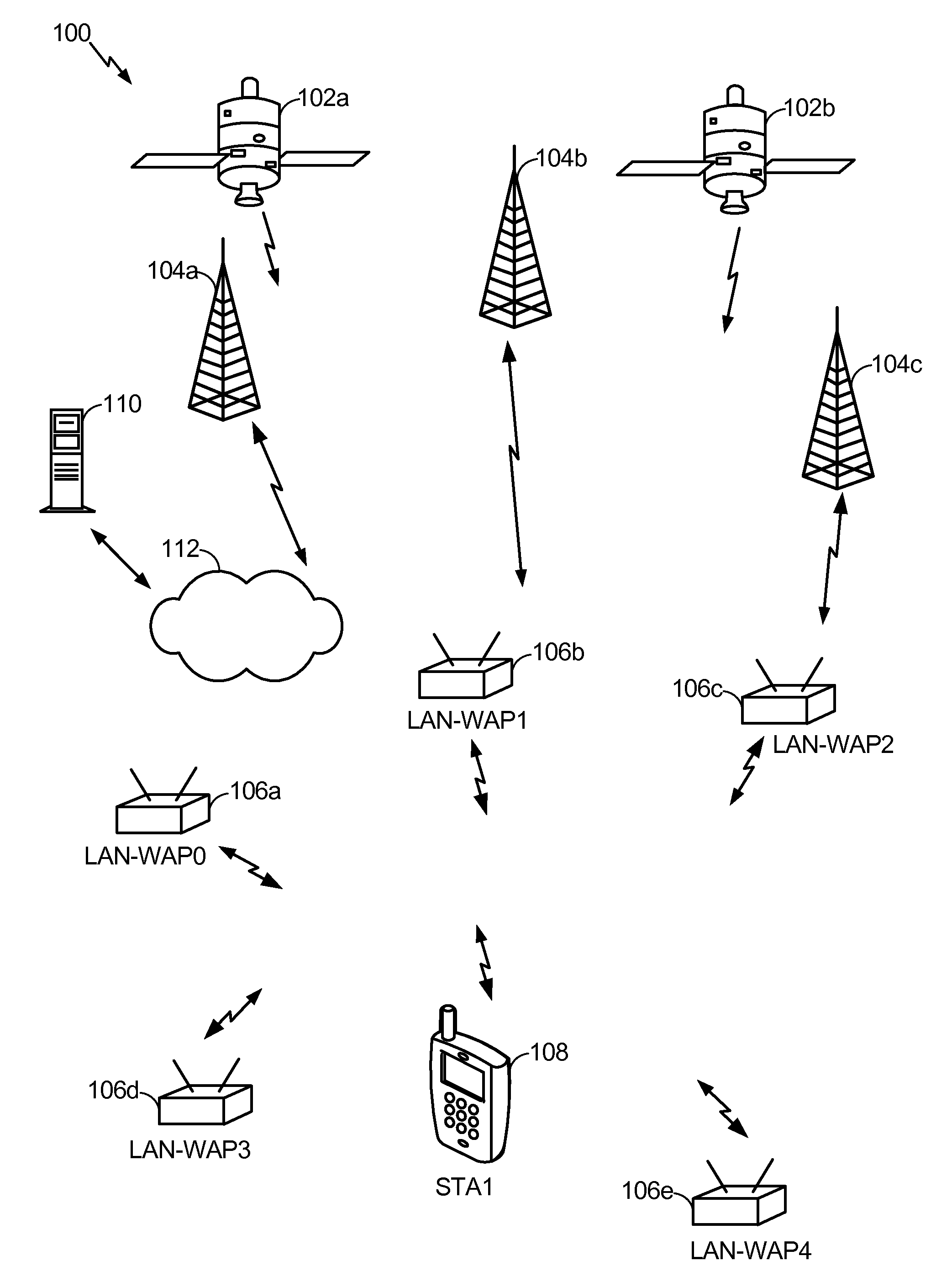
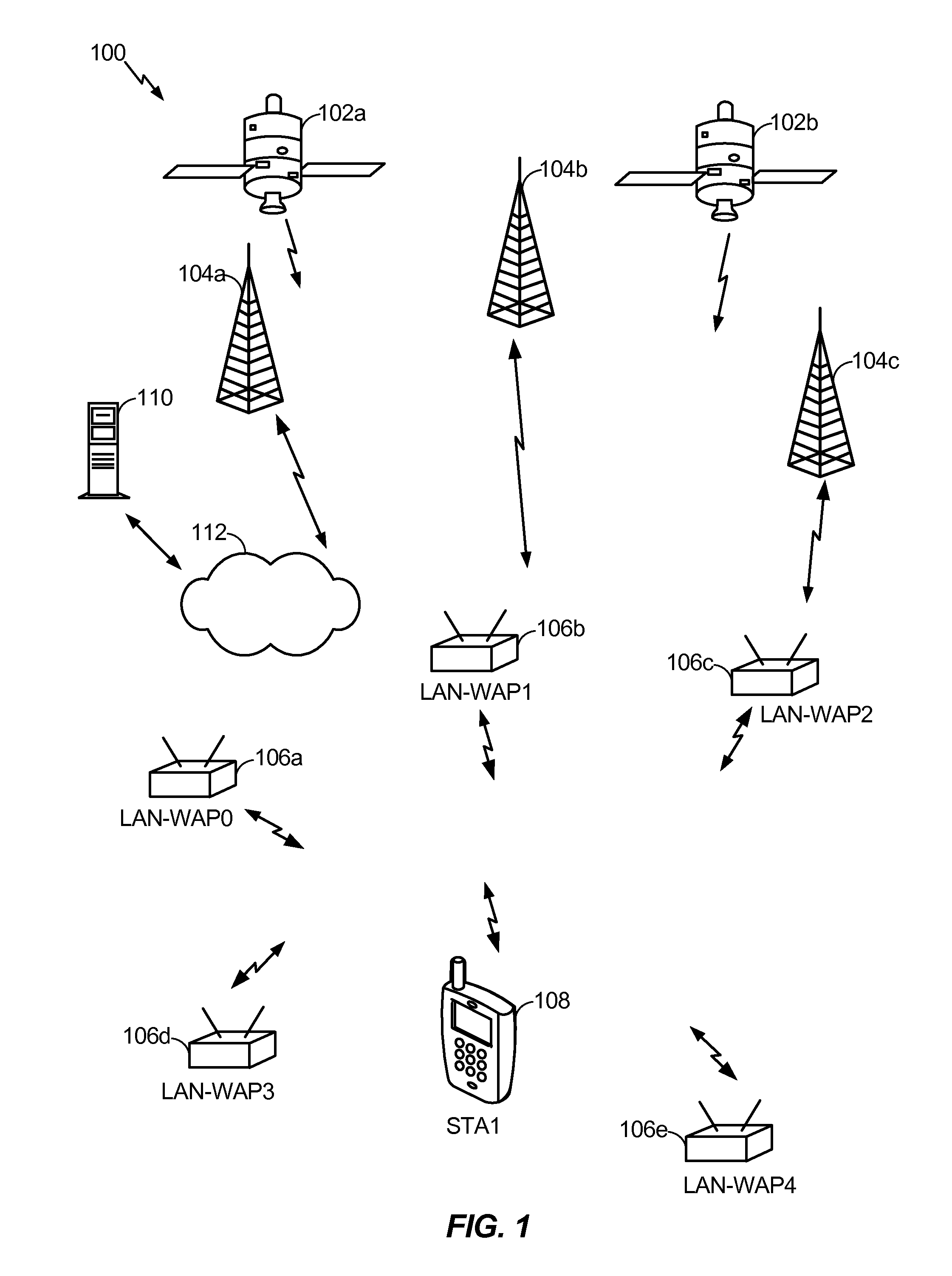
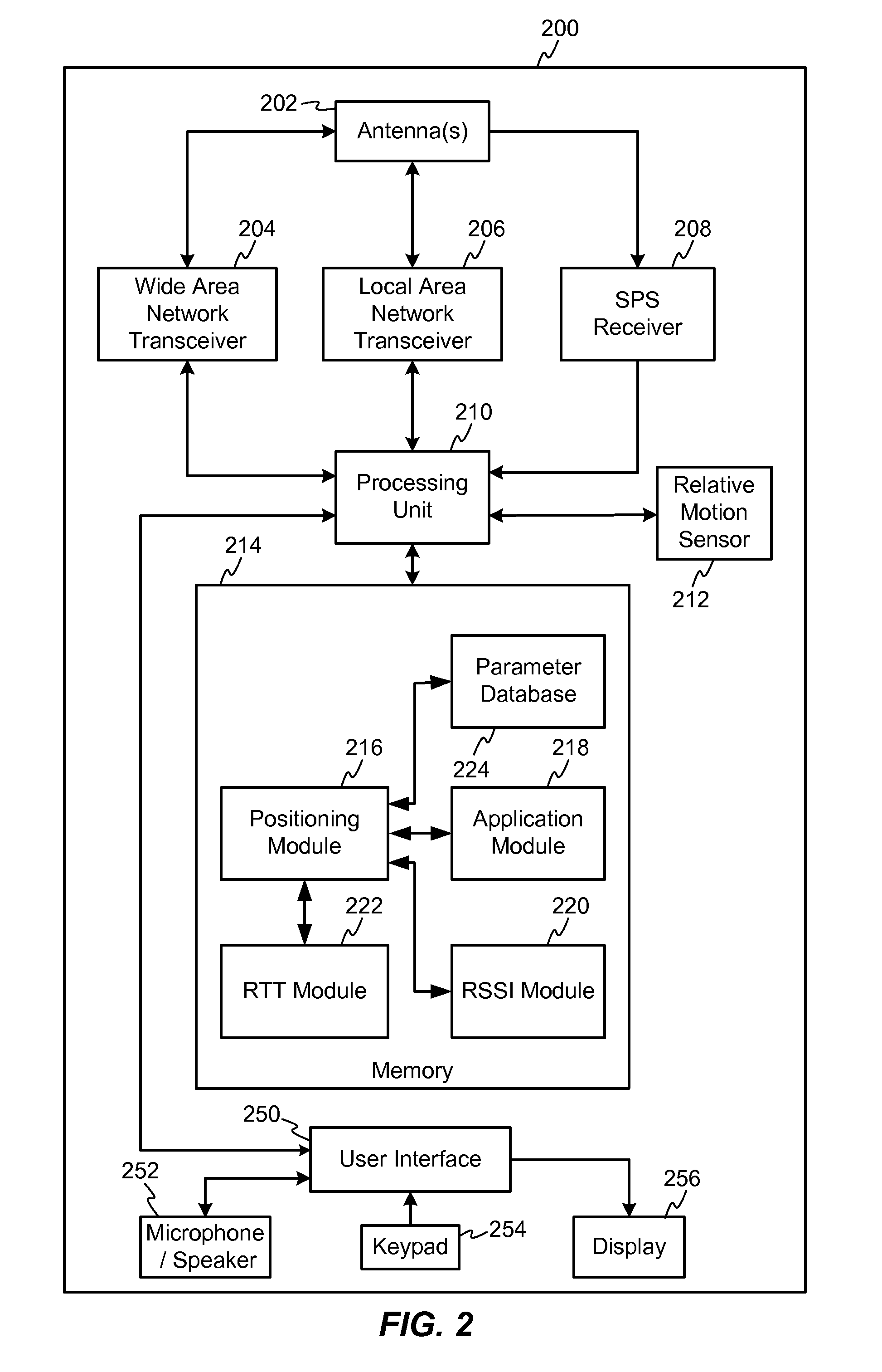
Exemplary embodiments of the invention are directed to a dedicated appliance and method for facilitating localization of a station (STA) in a wireless network, e.g., a short-range wireless network. An exemplary appliance can be capable of providing an automatic response to a request for a measurement related communication, such as a request for a round trip time (RTT) measurement from the STA and can include a radio frequency (RF) interface including a transceiver with a frequency conversion section and a media access control (MAC) section coupled to the RF interface. The appliance has a MAC address assigned thereto. The MAC section is configured to receive the request for the measurement related communication, generate the automatic response, such as an acknowledgement (ACK) (e.g., acknowledgement frame) to the received request for the measurement related communication immediately after a uniform predetermined period that is established within the short-range wireless network. The ACK may form the measurement related communication. The uniform predetermined period is associated with processing of the response in the appliance and is uniform among any appliance within the network. The automatic response can include the MAC address. It is important to note that in some embodiments the appliance is configured to perform only the generation of the automatic response, though the response may include additional information such as localization criteria such as (x, y) coordinate pair associated with a location of the appliance or a universal resource identifier (URI) or the like that has additional location information. For example, the URI may be associated with a resource containing additional location information. In other embodiments, the appliance can be configured to provide in, for example, a beacon, information such as (x, y) coordinates of the appliance or a universal resource identifier (URI) or the like that has additional location information before a request is generated for a measurement related communication.

Problems solved by technology

However, conventional position location techniques based upon signals provided by SPS and cellular base stations may encounter difficulties when the mobile station is operating within a building and within urban environments or in situations when high accuracy is desired.
In such situations, signal reflection and refraction, multipath, and signal attenuation, and the like can significantly reduce position accuracy, and can slow the “time-to-fix” to unacceptably long time periods.
In conventional networks, APs can be used for localization; however, the use of existing APs has several potential challenges.
It will be understood that, while 2 dimensional positioning requires at least three non-collinear APs, a particular geometry having three non-collinear APs may not be available in an existing deployment.
However, APs with adequate resources for localization may not be available in all deployment scenarios.
Further, heavy loading on a given AP such as processing a large memory transfer via direct memory addressing (DMA) may cause variation in the RTT turn-around time and thus degrade localization accuracy and stability.
Still further, contention may arise between the localization traffic and the normal data / control traffic if using a deployed AP for localization, leading to delay or loss of localization data.
However such configuration and updating may not be possible in all deployment scenarios.

Method used


Image

  • Device for round trip time measurements
  • Device for round trip time measurements
  • Device for round trip time measurements

Examples


Embodiment Construction

Aspects of the invention are disclosed in the following description and related drawings directed to specific embodiments of the invention. Alternate embodiments may be devised without departing from the scope of the invention. Additionally, well known elements of the invention will not be described in detail or will be omitted so as not to obscure the relevant details of the invention.

The word “exemplary” is used herein to mean “serving as an example, instance, or illustration.” Any embodiment described herein as “exemplary” is not necessarily to be construed as preferred or advantageous over other embodiments. Likewise, the term “embodiments of the invention” does not require that all embodiments of the invention include the discussed feature, advantage or mode of operation.

The terminology used herein is for the purpose of describing particular embodiments only and is not intended to be limiting of embodiments of the invention. As used herein, the singular forms “a”, “an” and “the...


PUM


Abstract

An appliance facilitates localization of a station (STA) in a network, for example, a short-range wireless network. An automatic response to a request for a measurement related communication is provided. The appliance can include a radio frequency (RF) interface and a media access control (MAC) section. The MAC section can receive the request and generate the automatic response immediately after a uniform period that is uniform among any such appliance within the network. The appliance performs only the generation of the automatic response, though the response can include additional information such as (x, y) coordinates of the appliance.

Description

BACKGROUND1. Background FieldAspects of the present disclosure generally relate to wireless communication systems, and more specifically, to position determination for mobile stations by facilitating accurate measurement of a round trip time (RTT) using a dedicated network appliance.2. Relevant BackgroundMobile communications networks are offering increasingly sophisticated capabilities associated with position location. New software applications, such as, for example, those related to personal productivity, collaborative communications, social networking, and data acquisition, may use position information to provide new features and services to consumers. Aside from the sizeable commercial potential, regulatory requirements in some jurisdictions may require a network operator to report the location of a mobile station when the mobile station places a call to an emergency service, such as a 911 call in the United States.Position determination has conventionally been provided using d...

Claims


Application Information

Patent Timeline
Patent Type & Authority Applications(United States)
IPC IPC(8): H04W64/00H04B17/00H04W4/80
CPCG01S5/14G01S13/82H04W24/10H04W24/00H04W84/10G01S13/46G01S2013/466H04W64/00H04W4/80H04L43/0864H04W88/02H04W64/003
Inventor DAS, SAUMITRA MOHANAGGARWAL, ALOKNAGUIB, AYMAN FAWZYHARDIE, EDWARD THOMAS LINGHAM
Owner QUALCOMM INC
Learn More