Row-running control system and vehicle

Active Publication Date: 2011-11-03
TOYOTA JIDOSHA KK
View PDF3 Cites 55 Cited by
  • Summary
  • Abstract
  • Description
  • Claims
  • Application Information

AI Technical Summary

Benefits of technology

[0011]According to the vehicle platooning control system and the vehicle of the i

Problems solved by technology

In this method, there is a problem in that a vehicle-to-vehicle distance error is propagated to the rear vehicle when the foremost vehicle is disturbed by a sl

Method used


Image

  • Row-running control system and vehicle
  • Row-running control system and vehicle
  • Row-running control system and vehicle

Examples


first embodiment

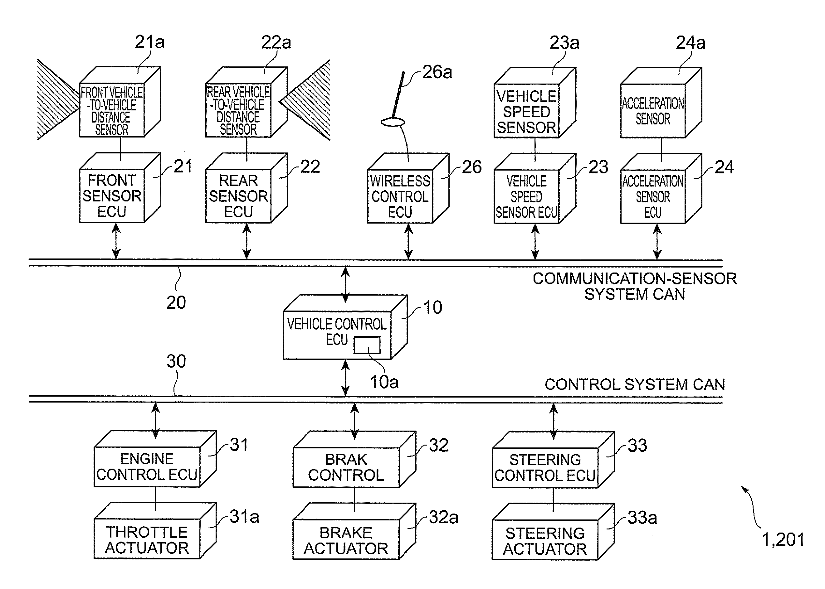
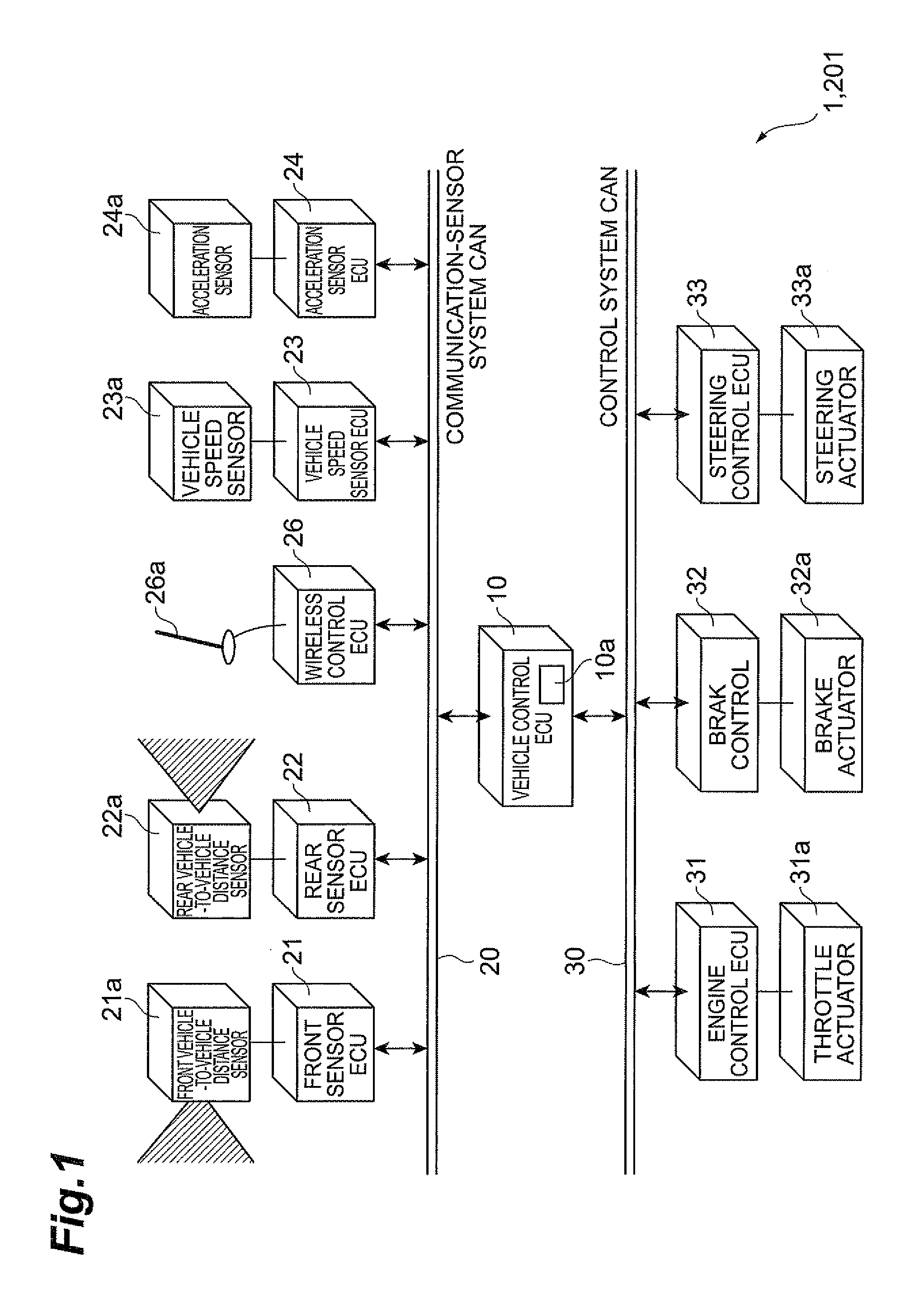
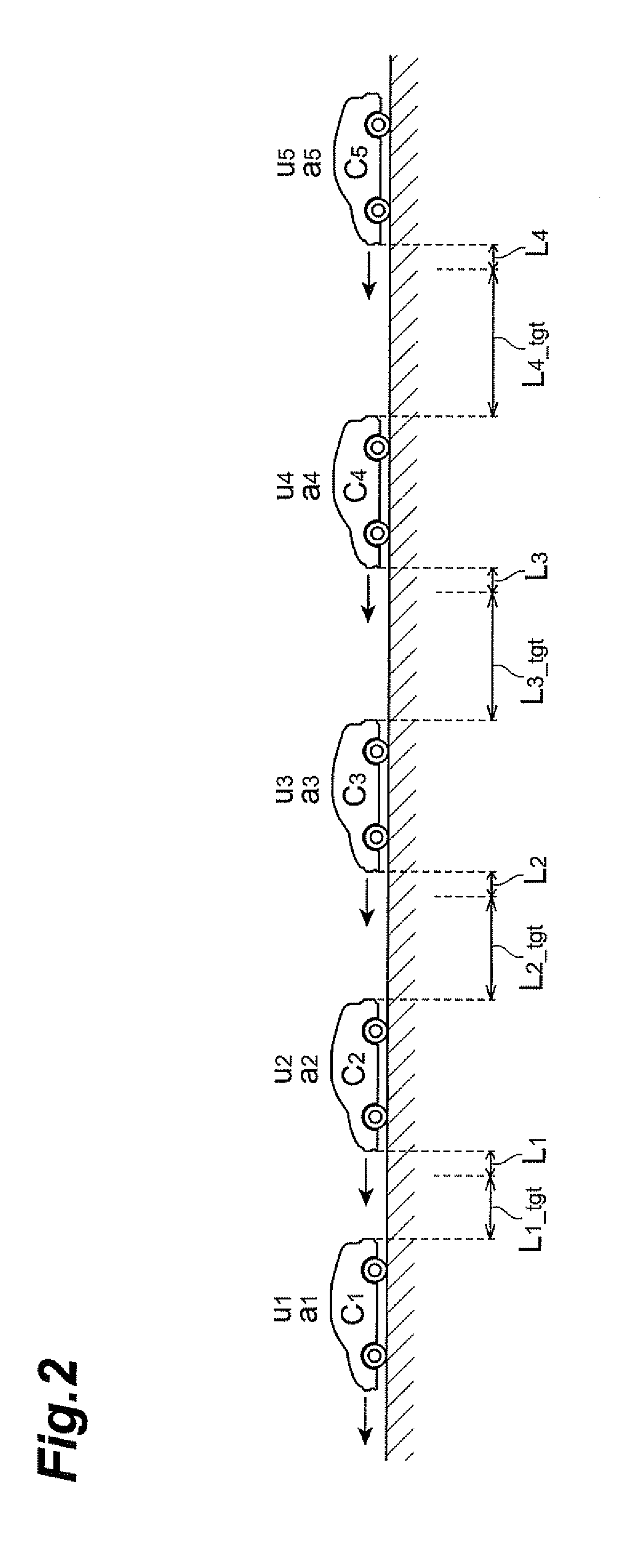
[0020]A vehicle platooning control system 1 shown in FIG. 1 is a system that controls each running state of a plurality of vehicles so that the plurality of vehicles runs in a row. By adopting the vehicle platooning control system 1, row-running may be realized in which the plurality of vehicles runs in a row with a comparatively narrow vehicle-to-vehicle distance. In the vehicle platooning control system 1, row-running of an arbitrary number of vehicles may be realized. However, here, as shown in FIG. 2, a case will be exemplified in which five vehicles C1, C2, C3, C4, and C5 run in a row.

[0021]Furthermore, in the description below, if necessary, as shown in FIG. 2, the acceleration of a vehicle Cn at n-th (n=1, 2, . . . , 5) from a foremost vehicle is denoted by “an”, the speed of the vehicle Cn is denoted by “Vn”, and the acceleration instruction value of the vehicle Cn is denoted by “un”. Further, the target vehicle-to-vehicle distance between the vehicle Cn and the vehicle Cn+1...

second embodiment

[0041]Next, a second embodiment of the vehicle platooning control system according to the invention will be described. Since the physical configuration of a vehicle platooning control system 201 of the embodiment is the same as that of the vehicle platooning control system 1 as shown in FIG. 1, the repetitive description thereof will be omitted.

[0042]As described above, in this kind of row-running, since the vehicle-to-vehicle error propagation ratio S is dependent on the acceleration frequency of the vehicle, there is an acceleration frequency of the vehicle making the vehicle-to-vehicle error propagation ratio S as S>1. For example, in the example of FIG. 3, the frequency around 6·10−2 Hz corresponds thereto. Likewise, the acceleration frequency of the vehicle making the vehicle-to-vehicle error propagation ratio S as S>1 will be referred to as an “inappropriate frequency”. As described above, when the foremost vehicle C1 increases or decreases speed with the appropriate frequency...


PUM


Abstract

A vehicle platooning control system is a vehicle platooning control system that controls a relative relationship between vehicles so that a plurality of vehicles runs in a row. In this system, each target value of a relative relationship between vehicles continuous in the longitudinal direction of a row is determined on the basis of a relative relationship error propagation ratio which is a ratio of an error of the relative relationship propagated to the rear vehicles running in the row.

Description

TECHNICAL FIELD[0001]The present invention relates to a vehicle platooning control system that controls a relative relationship between vehicles so that a plurality of vehicles runs in a row and a vehicle that includes the system.BACKGROUND ART[0002]In recent years, a technology of making a plurality of vehicles run in a row with a short vehicle-to-vehicle distance has gained attention in order to improve a traffic flow and improve fuel efficiency with a reduction of air resistance. Hitherto, there has been known a method of controlling a vehicle-to-vehicle distance between a front vehicle and each of subsequent vehicles of a row. In this method, there is a problem in that a vehicle-to-vehicle distance error is propagated to the rear vehicle when the foremost vehicle is disturbed by a slope of a road, a wind, or the like. In order to solve this problem, a system is proposed in JP-A-10-162282. In this system, the row-running of the plurality of vehicles is realized by controlling the...

Claims


Application Information

Patent Timeline
IPC IPC(8): G08G1/00B60W30/16
CPCB60W30/16G08G1/22B60W2550/408B60W2050/008B60W2556/65B60W2050/0075
Inventor SHIDA, MITSUHISA
Owner TOYOTA JIDOSHA KK
Why Eureka
Try Eureka