Damage resistant power transmission structures

a technology of power transmission structure and resistance, applied in the direction of electrical cable installation, overhead installation, adjusting/maintaining mechanical tension, etc., can solve the problems of sacrificing all the lighter structures in between, imposing significant costs on utilities and customers, and power transmission structure susceptible to progressive or cascading collapse, etc., to achieve fast and easy repair, eliminate dead-end structures, and economic to repair

Inactive Publication Date: 2011-11-10
IOWA STATE UNIV RES FOUND
View PDF33 Cites 7 Cited by
  • Summary
  • Abstract
  • Description
  • Claims
  • Application Information

AI Technical Summary

Benefits of technology

[0005]It is a further object, feature, or advantage of the present invention to provide power transmission structures which are reliable.
[0006]A still further object, feature, or advantage of the present invention is to provide power transmission structures which are resistant to collapse.
[0007]Another object, feature, or advantage of the present invention is to provide power transmission structures which are economical to repair.
[0008]Yet another object, feature, or advantage of the present invention is to provide power transmissions structures which can be quickly and easily repaired.
[0009]A still further object, feature, or advantage of the present invention is to provide power transmission structures which isolate the effects of extreme load events.
[0010]Yet another object, feature, or advantage of the present invention is to eliminate dead-end structures.

Problems solved by technology

Power transmissions structures are susceptible to progressive or cascading collapse stemming from a variety of catastrophic load events such as ice storms, extreme winds, impacts, ground movements, transmission line breaks, or sabotage.
The power outages that result from such events impose significant costs on utilities and customers.
Current structural design practice provides heavy, expensive dead-end structures spaced at approximately five to ten mile increments to contain a cascading collapse, thus sacrificing all the lighter structures in between.
Thus, the direct and indirect costs associated with such collapses can be tremendous.

Method used


Image

  • Damage resistant power transmission structures
  • Damage resistant power transmission structures
  • Damage resistant power transmission structures

Examples


Embodiment Construction

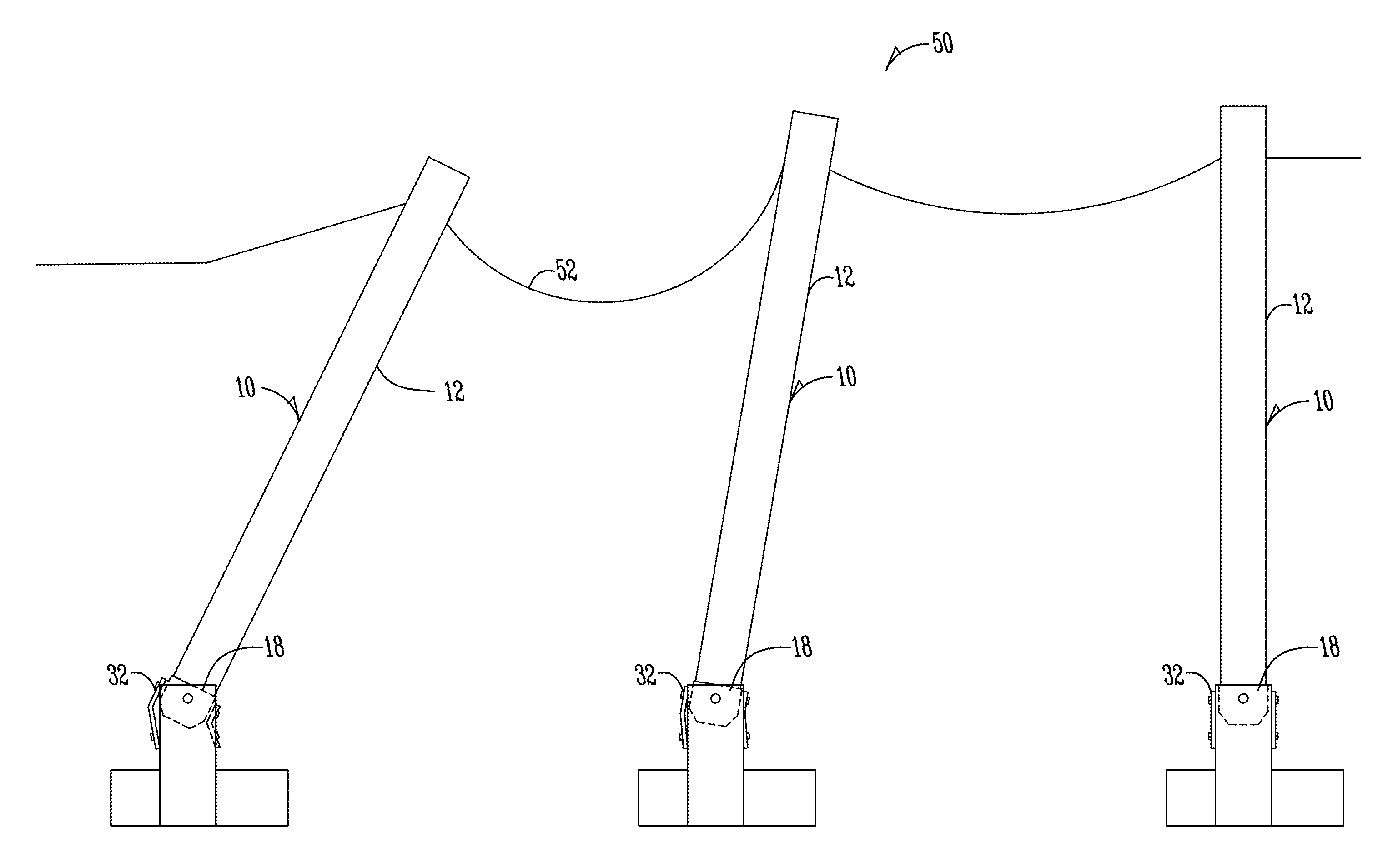
[0033]The present invention provides for improved overhead transmission line support structures. Each typical line structure is designed to maintain all or most of its maximum lateral load resistance over much larger lateral deflections parallel to the lines than possible with current designs. Thus, a damaged structure may share loads with adjacent structures and isolate the effects of an extreme load event instead of initiating a cascading collapse. Furthermore, the present invention allows damaged structures to be quickly and easily repaired, thus greatly reducing costs associated with such events.

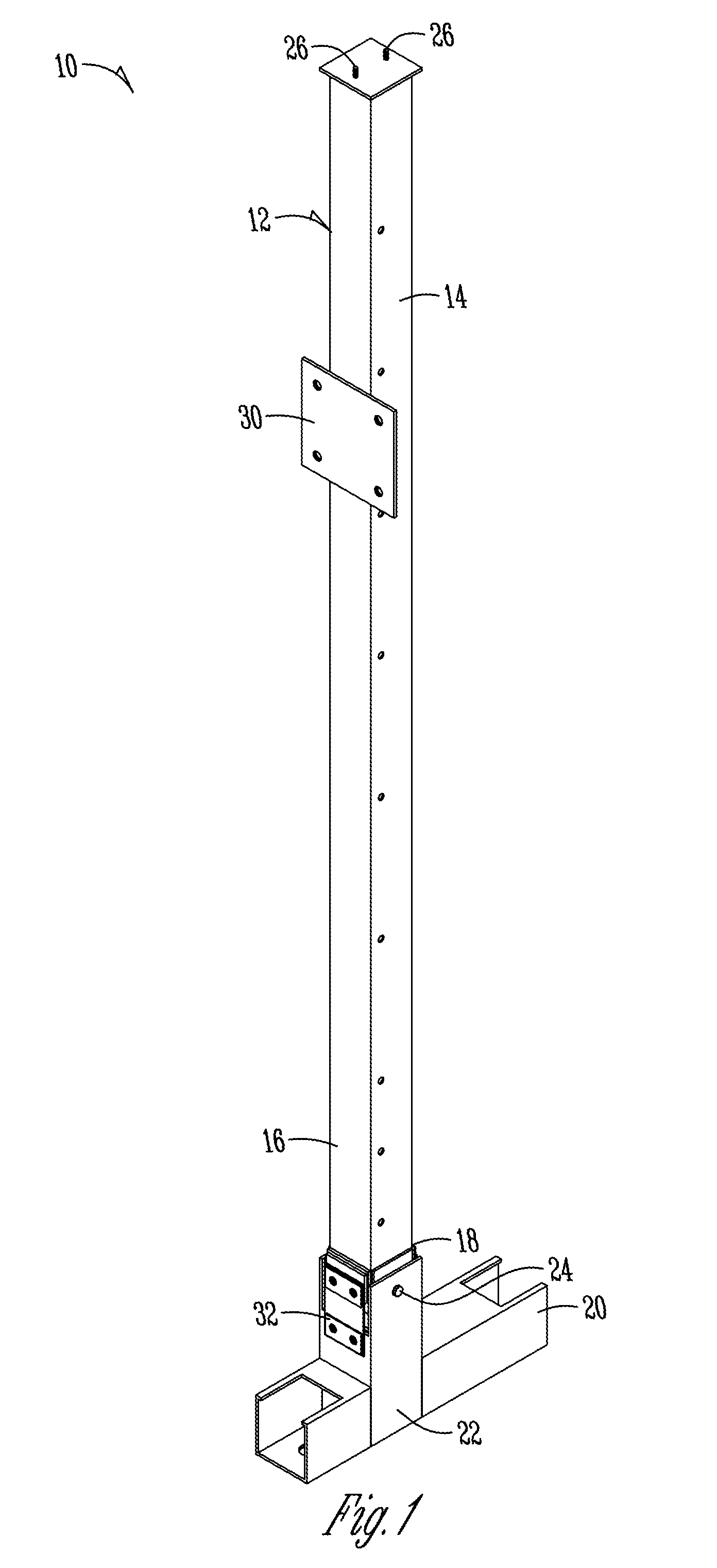
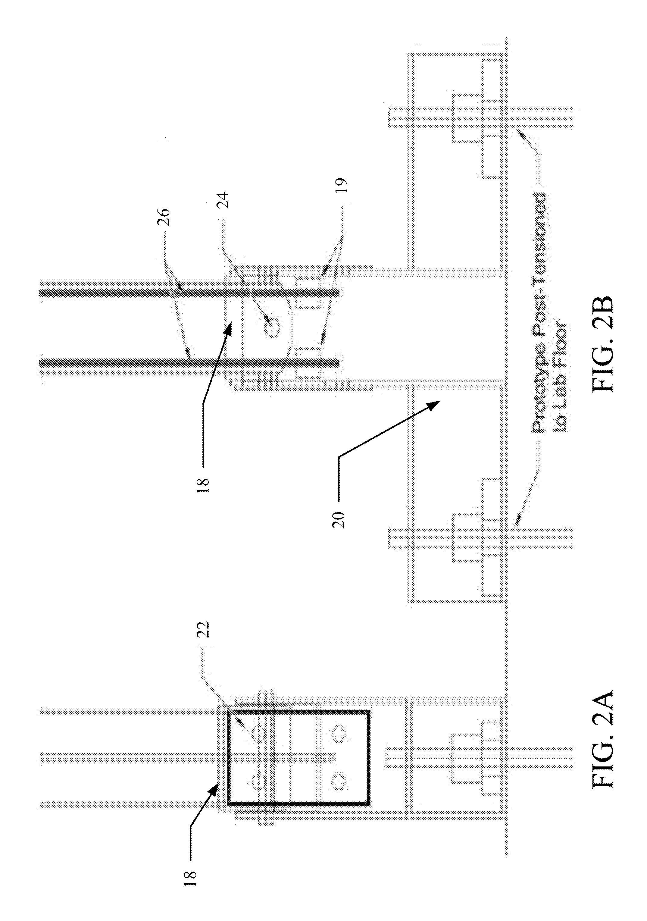
[0034]To attain the desired behavior, a pole system that employs elastic tendons and structural fuses is provided. The elastic tendons increase the overturning moment capacity of the structure and provide a self-centering force to right the pole when the extreme load is removed. The structural fuses are inexpensive, replaceable elements (such as external plates or bars) designed to form ...


PUM


Abstract

An overhead transmission line support structure includes a base segment and a main segment extending upwardly from the base segment. The overhead transmission line structure further includes a hinge operatively connecting the base segment with the main segment such that the hinge provides deflection capacity parallel to overhead transmission lines supported by the overhead transmission line support structure and such that with sufficient longitudinal loading on the overhead transmission line support structure, the main segment rotates about the hinge. The overhead transmission line support structure may include a post-tensioning system extending along the main segment and/or at least one fuse plate operatively connected between the base segment and the main segment and configured to deform upon the sufficient longitudinal loading on the overhead transmission line support structure.

Description

CROSS-REFERENCE TO RELATED APPLICATIONS[0001]This application claims priority under 35 U.S.C. §119 to provisional application Ser. No. 61 / 331,190 filed May 4, 2010, herein incorporated by reference in its entirety.FIELD OF THE INVENTION[0002]The present invention relates to damage resistant power transmission structures. More specifically, but not exclusively, the present invention relates to damage resistant power transmission structures which maintain maximum lateral load resistance over relatively large lateral deflections parallel to the attached wires.BACKGROUND OF THE INVENTION[0003]Power transmissions structures are susceptible to progressive or cascading collapse stemming from a variety of catastrophic load events such as ice storms, extreme winds, impacts, ground movements, transmission line breaks, or sabotage. The power outages that result from such events impose significant costs on utilities and customers. Current structural design practice provides heavy, expensive dea...

Claims


Application Information

Patent Timeline
Patent Type & Authority Applications(United States)
IPC IPC(8): H02G7/04
CPCH02G7/18H02G7/04
Inventor ROUSE, JON MATTHEWSFABER, CASEY VAUGHN
Owner IOWA STATE UNIV RES FOUND
Why Eureka
Try Eureka