
Gas spring

a gas spring and spring technology, applied in the direction of springs, liquid springs, vibration dampers, etc., can solve the problems of unsatisfactory, increase the service life and safety requirements, and easy to dismantle and replace worn parts

Active Publication Date: 2007-10-09
STROMSHOLMEN
View PDF14 Cites 2 Cited by
  • Summary
  • Abstract
  • Description
  • Claims
  • Application Information

AI Technical Summary

Benefits of technology

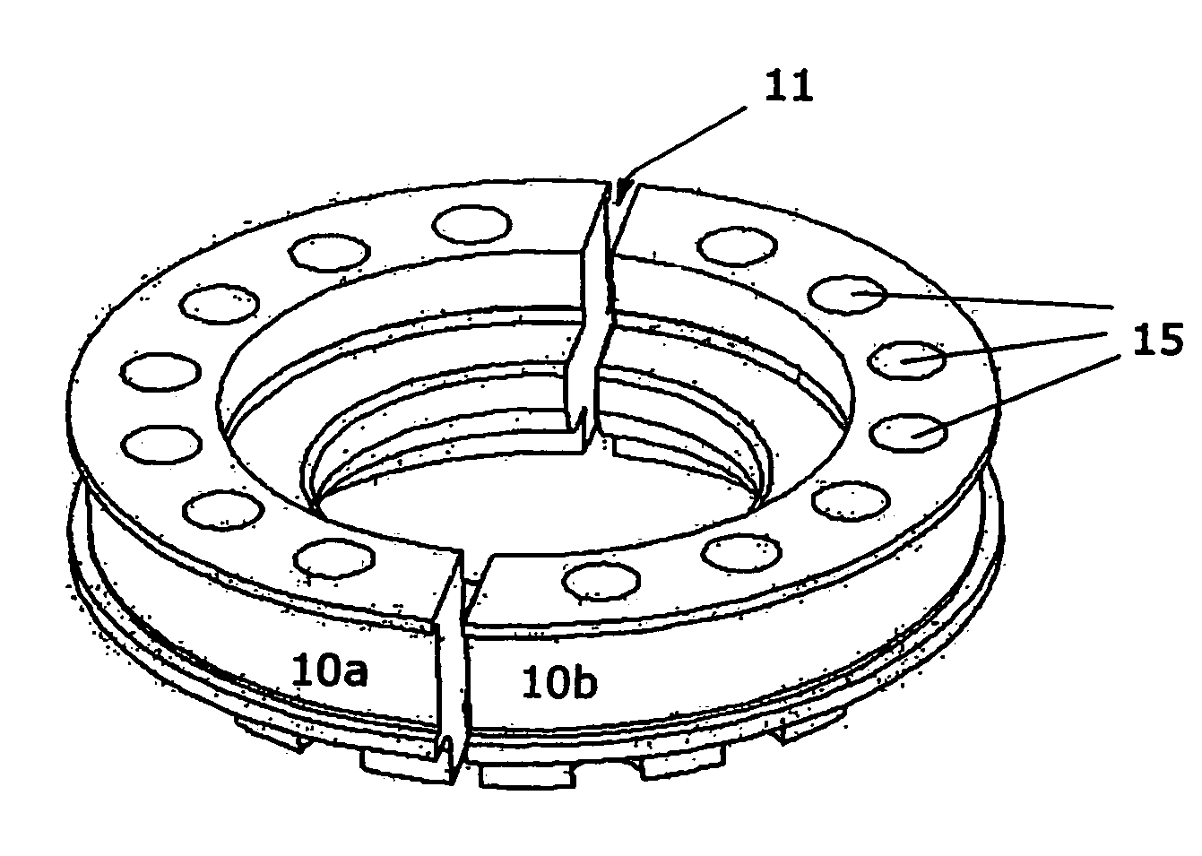
"The present invention relates to a gas spring for a pressing tool that reduces heat generation and pressure gradient, and improves the operating temperature and service life of the gas spring. The gas spring includes a tube, a piston, and a piston rod. The piston rod is axially moveable and supported so that it can slide in a piston rod guide at the first end wall of the tube. The gas spring also has passages that connect two spaces inside the tube, which allows gas to flow between the spaces. The cross-sectional area of the passages is at least 5% of the area of the piston to reduce heat generation. The invention also provides a method for reducing the pressure gradient between the two spaces in the gas spring. The gas spring can be easily disassembled and replaced before being re-fitted to the pressing tool again. The piston is designed to guide the end of the piston rod towards the center of the tube."

Problems solved by technology

An improvement is obtained just by increasing the passage area to 5%, but this is not ideal since the reduction in the operating temperature of the gas spring is insufficient.

Method used


Image

  • Gas spring
  • Gas spring
  • Gas spring

Examples


Embodiment Construction

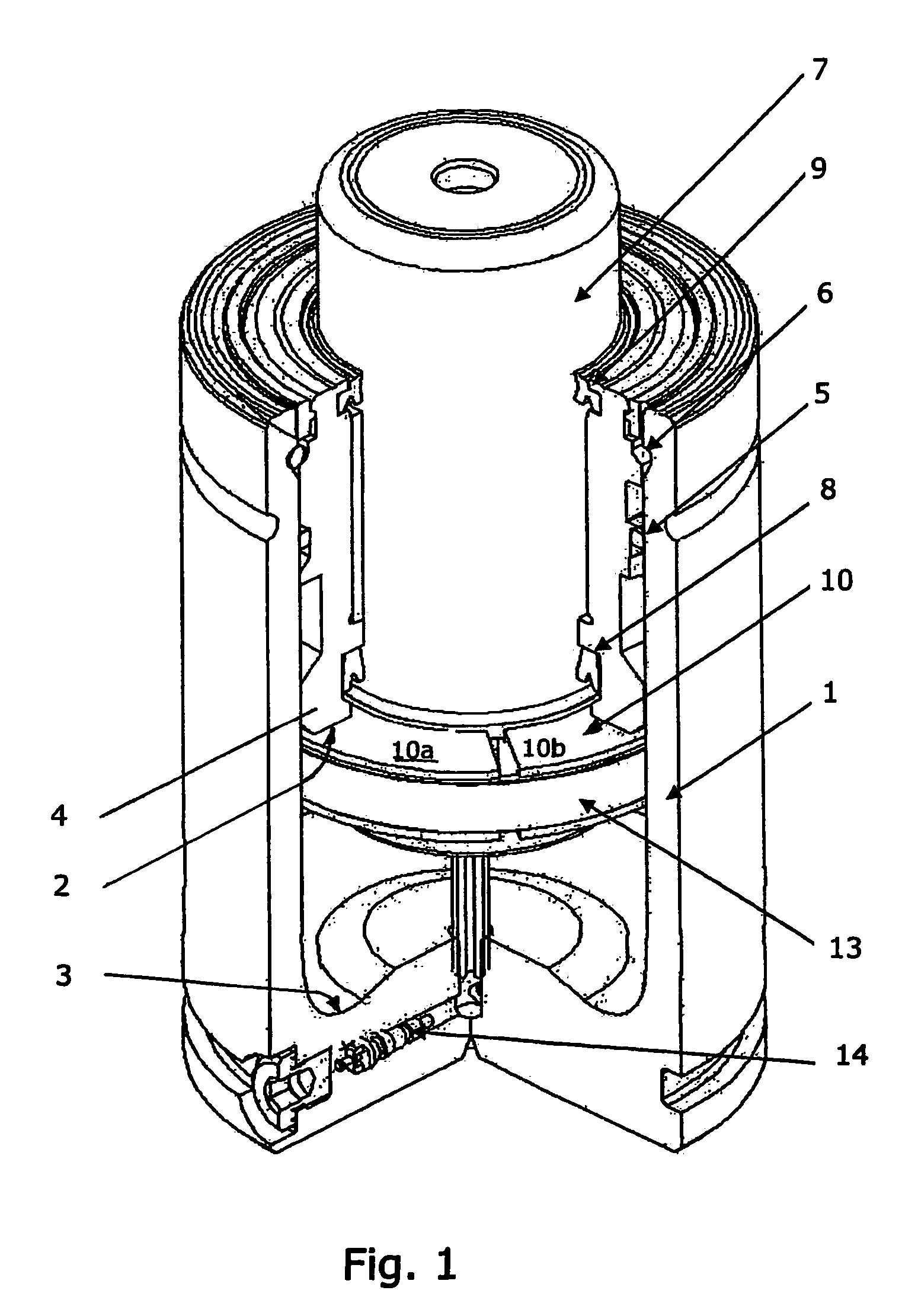
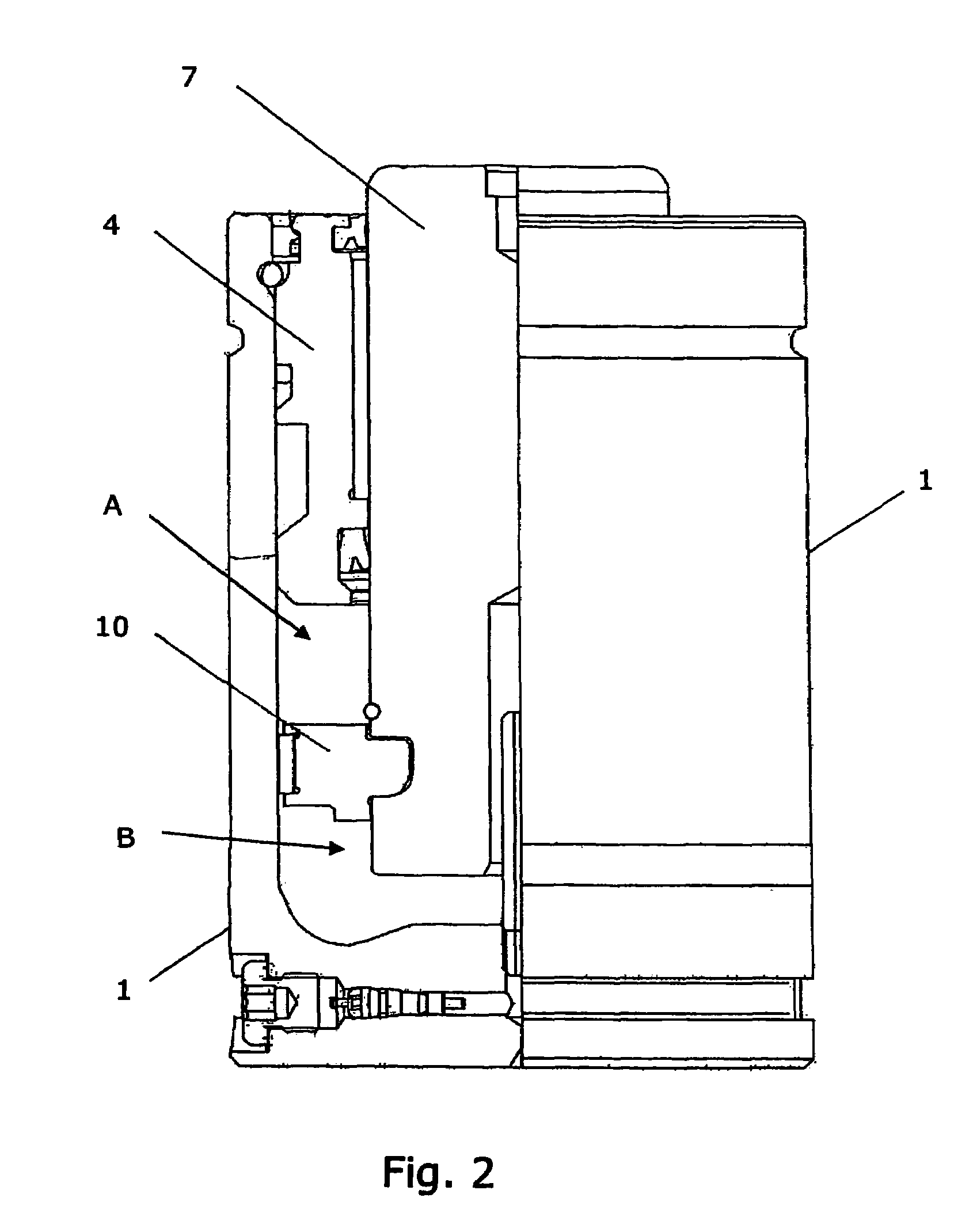
[0032]A number of embodiments of the invention are described below with reference to the drawings attached.

[0033]FIG. 1 depicts a gas spring of conventional type. A cylindrical tube 1 forms the cylindrical casing of the gas spring and thereby the wall of the cylindrical chamber of the gas spring. The cylindrical chamber is defined by two end walls, a first end wall 2 and a second end wall 3. In the embodiment shown the end wall 2 comprises a piston rod guide 4, which is inserted and sealed in relation to an open end of the tube 1 by means of a static seal 5 and is furthermore locked against the tube 1 by means of a locking ring 6. The other end wall 3 comprises a dosed part firmly connected to the tube 1. Running in the piston rod guide 4 is a piston rod 7, which is axially moveable along the axis of the cylindrical chamber and is supported so that it can slide in the piston rod guide 4 and is sealed off against this by means of a dynamic seal 8. A scraper 9 on the outer part of the...


PUM


Abstract

A gas spring for a pressing tool. A cylindrical chamber is divided by a piston into a first space and a second space. The piston is attached to a piston rod, which is axially moveable in the cylindrical chamber. The gas spring is designed with an opposing force to counteract a movement that is produced by forces acting axially on the piston rod in that the first space and the second space are pressurized with a gas. Passages connect the first space and the second space and permit a flow of gas between the first space and the second space. The passages occupy an area that is greater than 5% of the area of the piston in order to reduce the amount of heat generated in the gas spring. The area of the piston is the difference between the cross-sectional areas of the cylindrical chamber and the piston rod.

Description

TECHNICAL FIELD[0001]The present invention relates to a gas spring for a pressing tool, in which the design construction is improved in such a way that a lower operating temperature can be achieved at high loads.PRIOR ART[0002]Gas springs have come to be widely used throughout industry. One example are pressing tools intended for forming sheet-metal parts in which gas springs are nowadays mainly used for the various spring functions that are required. Thus gas springs are used, for example, for securing sheet metal, returning shuttles and separating tool halves in the pressing process. Gas springs which support a blank holder for pressing sheet metal are loaded at the beginning of the pressing process and relieved by the upward movement of a press slide and / or a press upper part after sheet metal forming. The proportion of the stroke length of a gas spring that is subject to loading is governed by the pressing process and the ultimate appearance of the pressed sheet-metal part. In o...

Claims


Application Information

Patent Timeline
Patent Type & Authority Patents(United States)
IPC IPC(8): F16F9/18F16F9/06F16F9/32F16F9/34F16F9/43
CPCF16F9/061F16F9/068F16F9/435F16F9/3405F16F9/3214F16F9/0218F16F9/00F16F9/34
Inventor CRONHOLM, MARCUSLUNDAHL, LEIFAXELSSON, JAKOB
Owner STROMSHOLMEN
Learn More