Repair method

a technology of repair method and repair method, which is applied in the field of repair method, can solve the problems of gas turbine components, gas turbine blades of integrally bladed gas turbine rotors, wear and tear of gas turbine blades, etc., and achieve the effects of high contour precision, good reproducibility, and high quality of thereby forming material structures

Inactive Publication Date: 2014-04-29
MTU AERO ENGINES GMBH
View PDF21 Cites 0 Cited by
  • Summary
  • Abstract
  • Description
  • Claims
  • Application Information

AI Technical Summary

Benefits of technology

[0009]The method according to the present invention makes it possible to realize a repair of gas turbine components while ensuring a high contour precision. A damaged portion, which has been removed from a gas turbine component to be repaired, may be renewed built up anew using as little over-allowance as possible. Another advantage of the method according to the present invention resides in that a high quality of the thereby forming material structure may be ensured. The method according to the present invention is automatable and, therefore, renders possible a good reproducibility. In addition, in comparison to other repair methods, the method according to the present invention makes it possible for gas turbine components to be repaired inexpensively.

Problems solved by technology

Gas turbine components, such as gas turbine blades of an integrally bladed gas turbine rotor, for example, are subject to wear during operation.
The wear can necessitate that the gas turbine components be repaired once they are damaged, in that damaged portions of the gas turbine components are removed from the same, and replaced following removal thereof.
Thus, for example, the rotor-side moving blades of integrally bladed gas turbine rotors are subject during operation to wear, in particular caused by oxidation, corrosion, erosion, as well as due to bird impact or hailstorms, thereby necessitating removal of damaged portions thereof, and replacement of the same following removal thereof.
Stator-side components, such as guide vanes or housing structures, for example, are also subject to wear that can necessitate a repair of the same.
However, when laser powder deposition welding is used for the repair, it is difficult to ensure an adequate contour precision.

Method used


Image

  • Repair method
  • Repair method
  • Repair method

Examples


Embodiment Construction

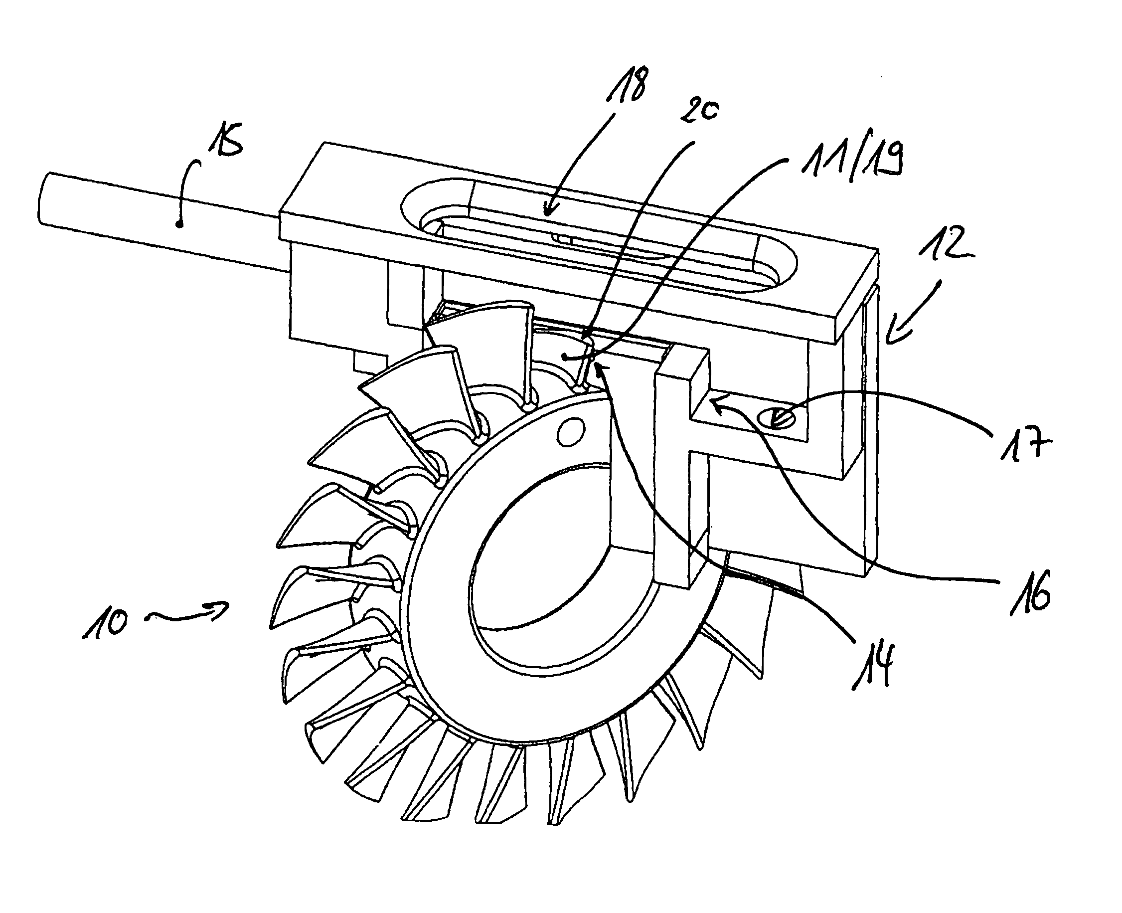
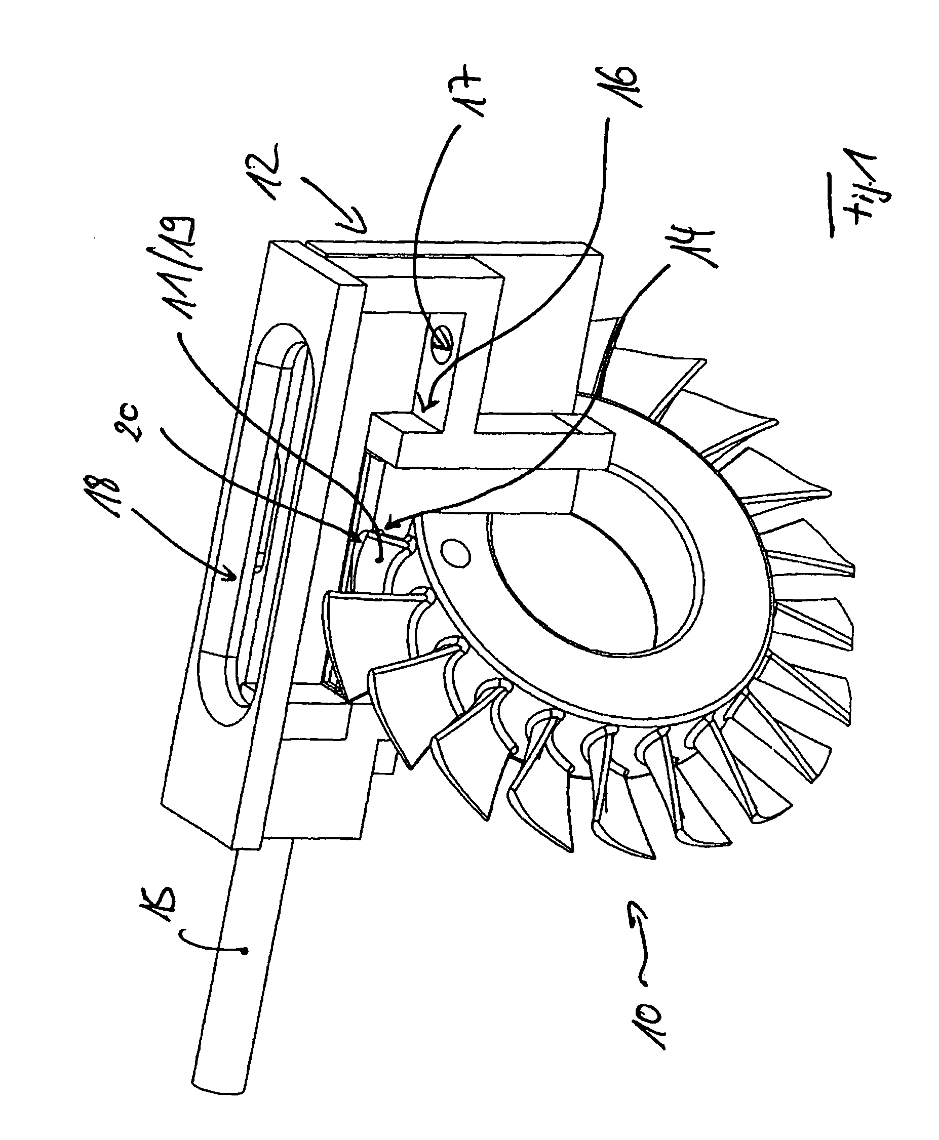
[0015]The present invention relates to a method for repairing gas turbine components, in particular gas turbine blades. The method is particularly suited for repairing gas turbine blades of an integrally bladed gas turbine rotor and for repairing complex housing structures of a gas turbine.

[0016]In a first step of the method according to the present invention, a gas turbine component to be repaired is prepared. In a subsequent second step of the method according to the present, a damaged portion is removed from the gas turbine component to be repaired, forming, namely, an approximately plane separation surface.

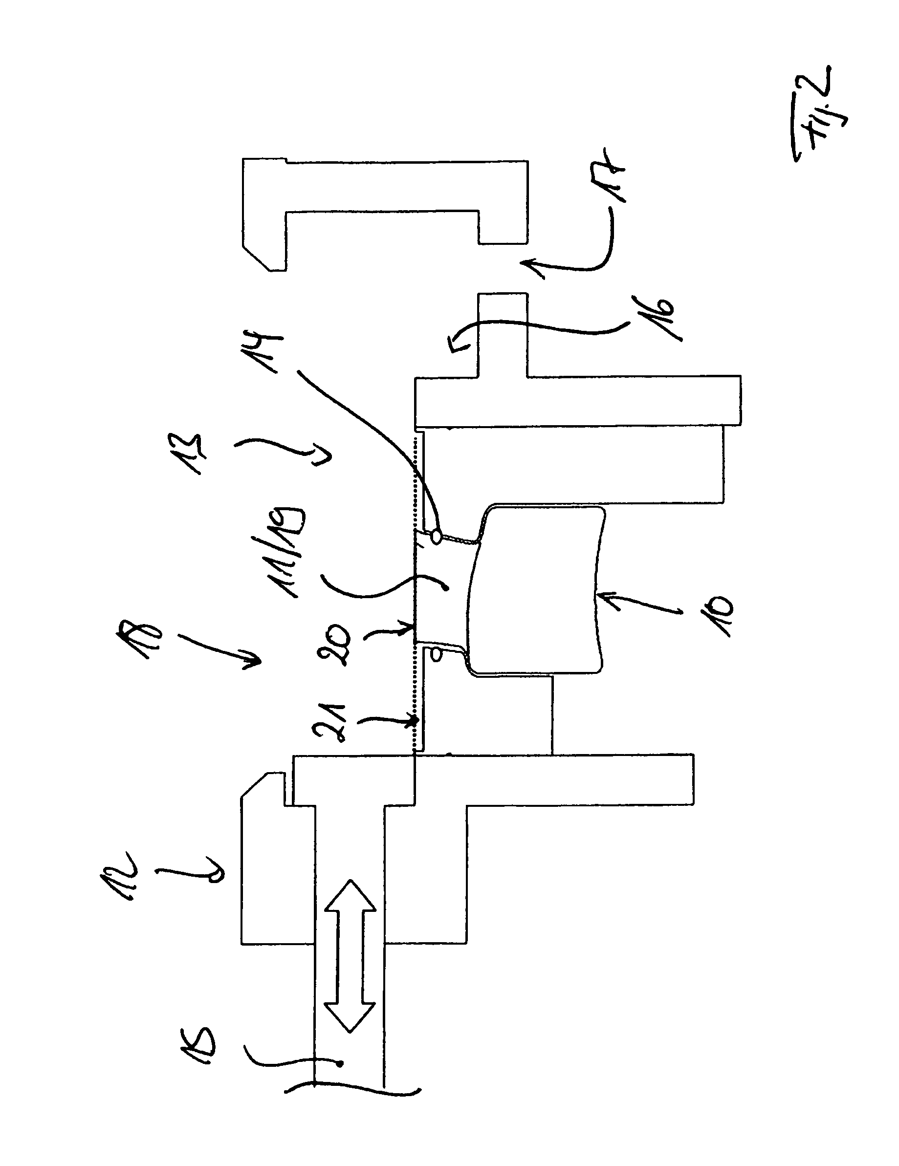
[0017]Once the damaged portion is removed from the component to be repaired, thereby forming the plane separation surface, the gas turbine component to be repaired is positioned in a third step, at least partly, in a process chamber, namely, in such a way that the plane separation surface is oriented, respectively extends approximately horizontally.

[0018]Subsequently thereto, ...


PUM

PropertyMeasurementUnit
corrosionaaaaaaaaaa
structureaaaaaaaaaa
areaaaaaaaaaaa

Abstract

A method for repairing gas turbine components, in particular gas turbine blades, including at least the following steps: a) preparing a gas turbine component to be repaired; b) removing a damaged portion from the gas turbine component to be repaired, thereby forming a plane separation surface; c) placing the gas turbine component at least partly in a process chamber in such a way that the plane separation surface extends approximately horizontally within the process chamber; d) filling the process chamber with a metal powder that is bonding-compatible with the material of the gas turbine component to be repaired, namely up to the level of the separation surface; e) building up the removed portion on the separation surface by depositing metal powder in layers onto the separation surface and by fusing the metal powder, which has been deposited in layers onto the separation surface, to the separation surface.

Description

[0001]The present invention relates to a repair method for gas turbine components, in particular for gas turbine blades. Moreover, the present invention relates to a process chamber used for the repair method according to the present invention.[0002]Gas turbine components, such as gas turbine blades of an integrally bladed gas turbine rotor, for example, are subject to wear during operation. The wear can necessitate that the gas turbine components be repaired once they are damaged, in that damaged portions of the gas turbine components are removed from the same, and replaced following removal thereof.BACKGROUND[0003]Thus, for example, the rotor-side moving blades of integrally bladed gas turbine rotors are subject during operation to wear, in particular caused by oxidation, corrosion, erosion, as well as due to bird impact or hailstorms, thereby necessitating removal of damaged portions thereof, and replacement of the same following removal thereof. Stator-side components, such as g...

Claims


Application Information

Patent Timeline
Patent Type & Authority Patents(United States)
IPC IPC(8): B29C43/02
CPCF05D2230/68B22F2999/00B22F2998/00B22F2202/13B22F7/062B22F5/04F01D25/285B22F3/1055F05D2230/31F01D5/005B22F3/003B23P6/007F05D2230/80Y02P10/25B22F10/28B22F10/73
Inventor HUTTNER, ROLANDDUSEL, KARL-HEINZBAYER, ERWINPLATZ, ALBIN
Owner MTU AERO ENGINES GMBH
Why Eureka
Try Eureka