Shaped coils for transcranial magnetic stimulation

a transcranial magnetic stimulation and coil technology, applied in the direction of coils, basic electric elements, therapy, etc., can solve the problems of limited depth and shape of emitted field, difficult to achieve focal brain stimulation at the cortical surface, and unoptimized magnetic field projected from standard figure-8 shaped double coil electromagnets, etc., to achieve superior magnetic field profiles and improve penetration to depth

Active Publication Date: 2011-11-10
BRAINSWAY
View PDF13 Cites 44 Cited by
  • Summary
  • Abstract
  • Description
  • Claims
  • Application Information

AI Technical Summary

Problems solved by technology

The magnetic field projected from standard figure-8 shaped double coil electromagnets is not optimal for deep brain stimulation, however.
In particular, the depth and shape of the emitted field is limited.
This makes focal stimulation of the brain challenging to achieve at the cortical surface (beneath scalp, skull and meninges), and even more difficult beneath the cortical surface.
However, the proposed designs described above each have substantial disadvantages, particularly with regard to the specificity and control of the magnetic field generated, as well as the ease with which these magnets may be fabricated and characterized.
This balance has been particularly difficult to achieve with known TMS electromagnets, yet is of great importance when the target is below the cortical surface of the brain.

Method used


Image

  • Shaped coils for transcranial magnetic stimulation
  • Shaped coils for transcranial magnetic stimulation
  • Shaped coils for transcranial magnetic stimulation

Examples


Embodiment Construction

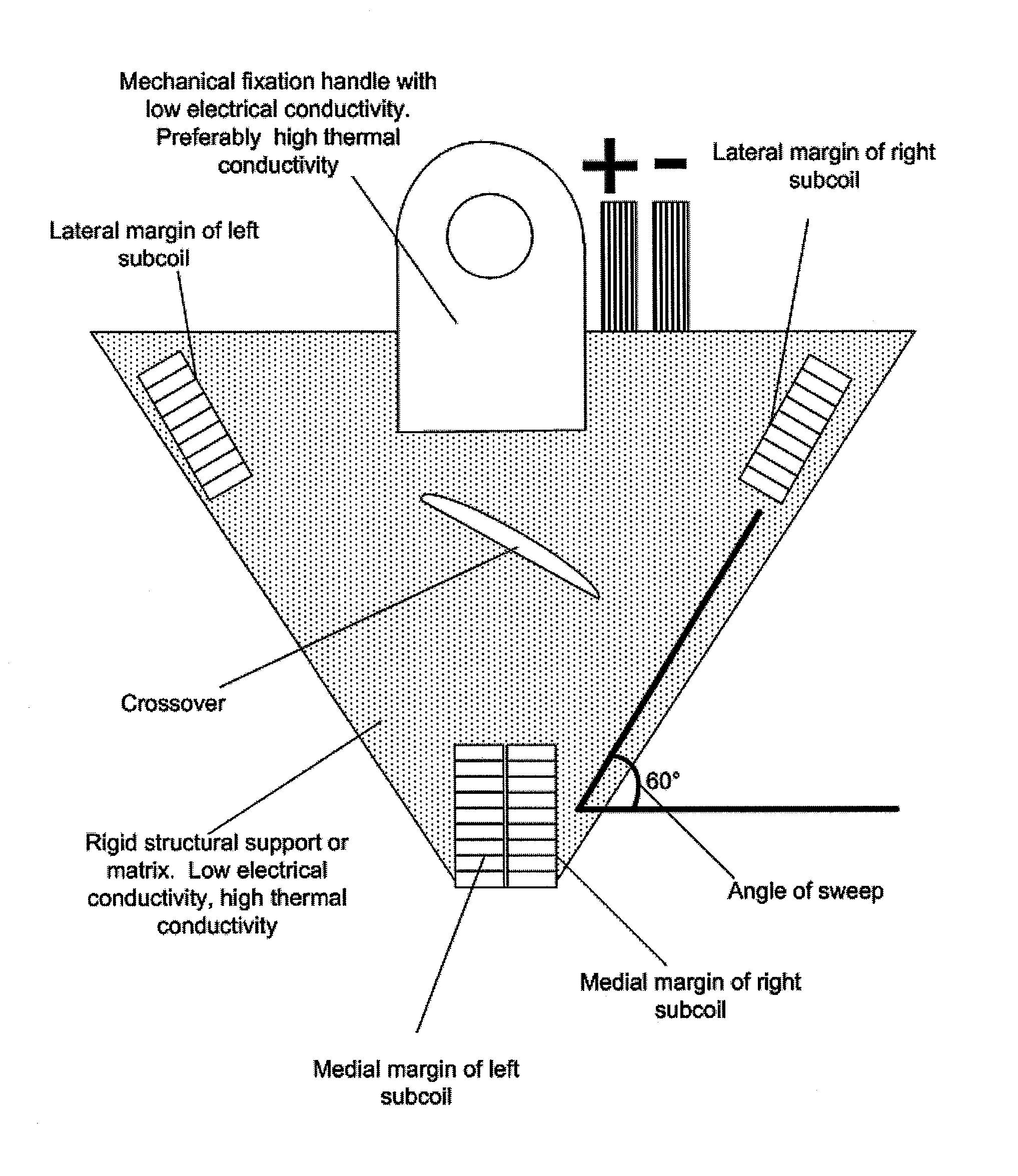
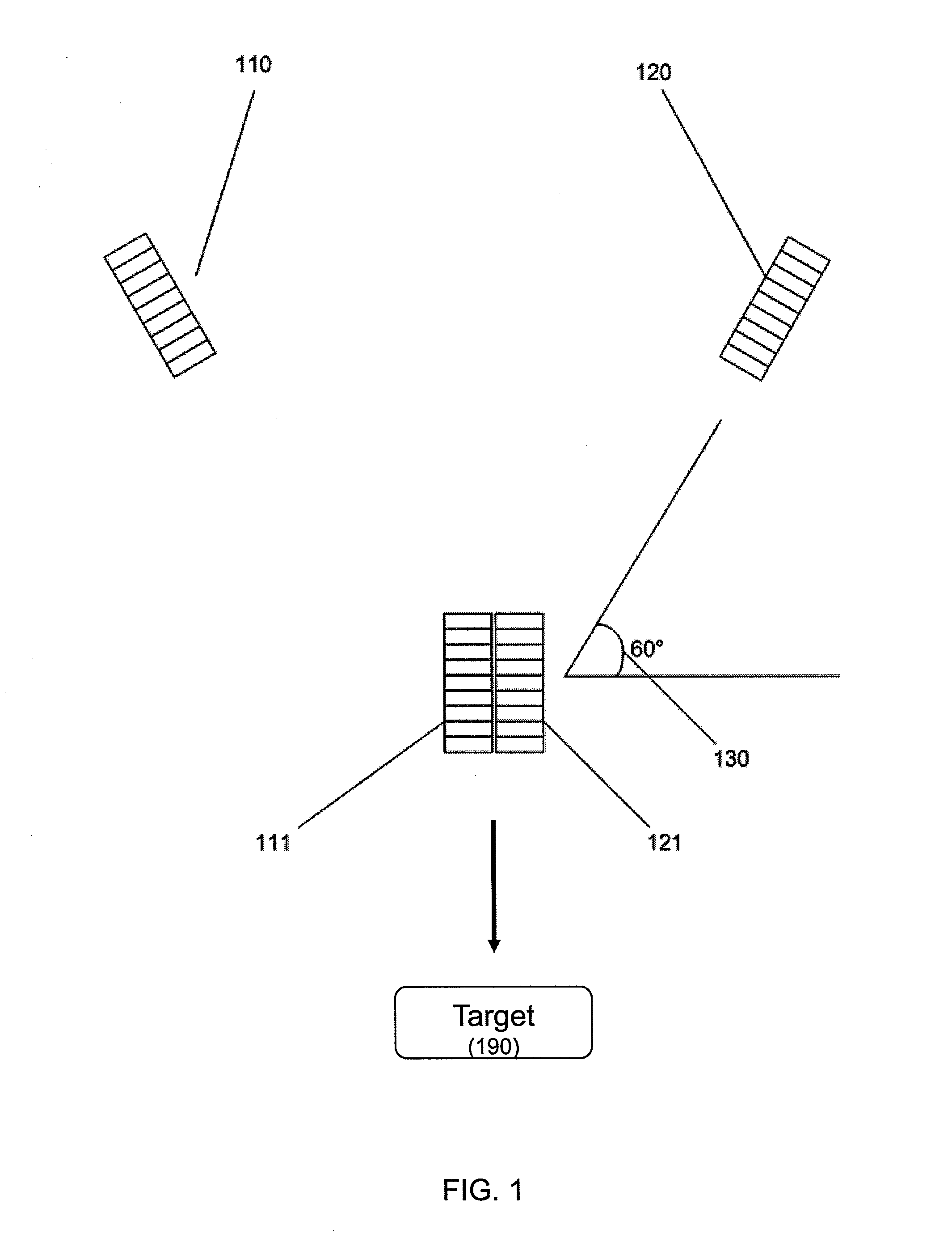
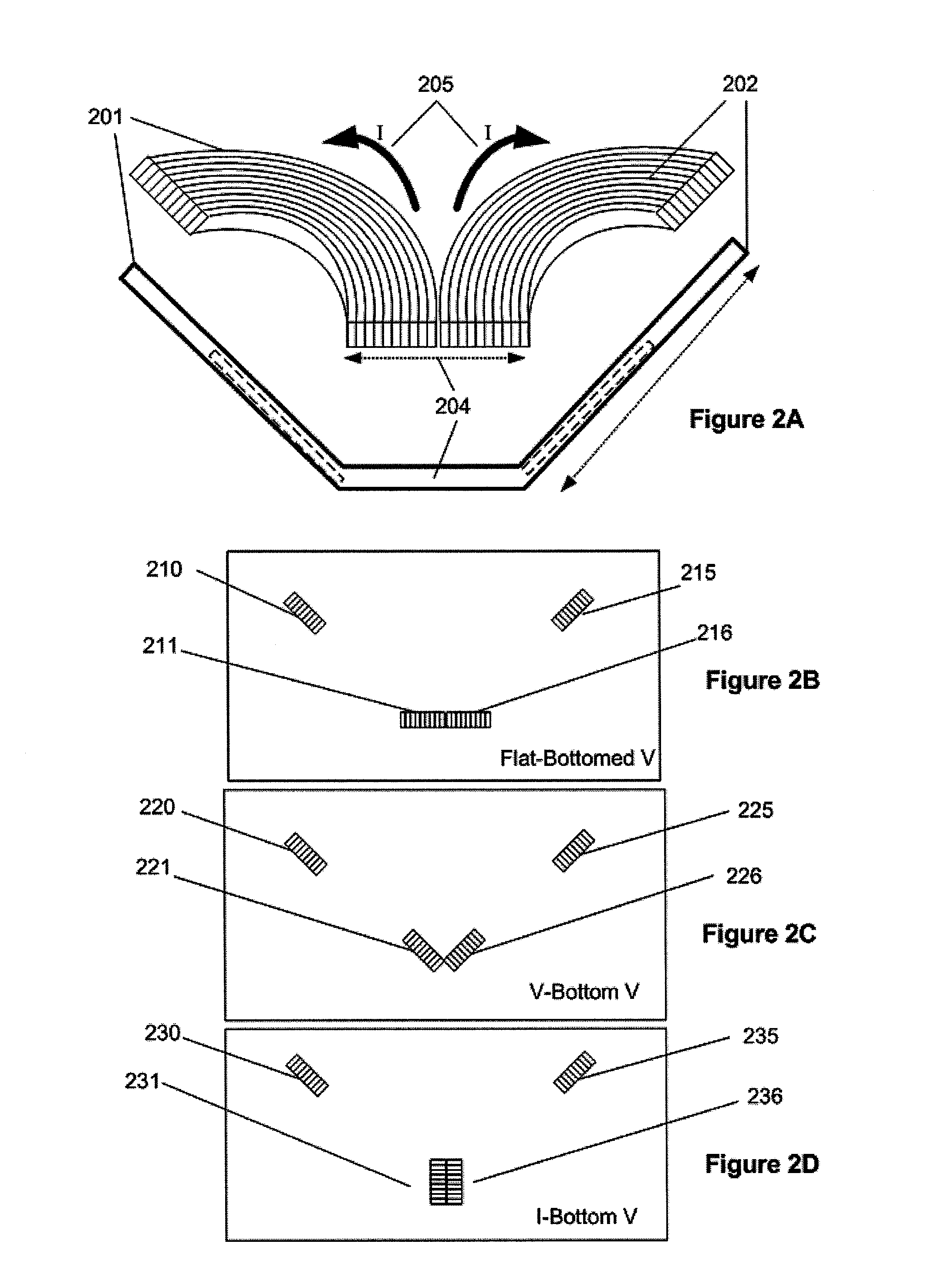
[0036]In general, the TMS magnets described herein may be referred to as shaped-coil TMS magnets. A shaped-coil TMS magnet typically includes a pair of coils (each having multiple windings) that have a non-flat shape and are connected to each other at a vertex region or point. A shaped coil may have a bent or curved ring shape. The shaped coils described herein may also be referred to as “V-shaped” coils.

[0037]Prior art TMS magnets having a two coils were typically “flat,” forming a “figure-8” shape. The shaped-coil TMS magnets described herein generally have two coils that are at an angle with each other that is less than 180 degrees (an angle of 180 degrees corresponds to the standard “figure-8” shaped coils), and an angle with respect to a horizontal plane that is greater than zero (e.g., a standard “figure-8” shaped coil has an angle of 0 degrees with respect to the horizontal). The vertex region, which may also be referred to as the ‘bottom’ of the shaped coil pairs, may be fla...


PUM

PropertyMeasurementUnit
angleaaaaaaaaaa
angleaaaaaaaaaa
angleaaaaaaaaaa

Abstract

Described herein are shaped coil TMS electromagnets formed by two bent magnetic coil loops joined at a vertex having an angle between the outer coil regions of the coils that is typically less than 120 degrees (e.g., between about 45 and about 70 degrees, 60 degrees, etc.). The vertex region shaped to optimize the magnetic field projected from the TMS electromagnet. For example, the vertex region may be horizontal or vertical. In some variations the vertex region is formed by re-arranging the conductive windings forming the two coils so that they are no longer arranged in the same columnar structure that they are in the other portions of the bent magnetic coil loops. These TMS electromagnets may be well suited for use in deep-brain Transcranial Magnetic Stimulation.

Description

CROSS REFERENCE TO RELATED APPLICATIONS[0001]This application claims priority to U.S. Provisional patent application Ser. No. 61 / 143,103, titled “SHAPED COILS FOR TRANSCRANIAL MAGNETIC STIMULATION”, filed on Jan. 7, 2009.INCORPORATION BY REFERENCE[0002]All publications and patent applications mentioned in this specification are herein incorporated by reference in their entirety to the same extent as if each individual publication or patent application was specifically and individually indicated to be incorporated by reference.FIELD OF THE INVENTION[0003]The devices and methods described herein relate generally to the focusing of magnetic fields generated by electromagnets used for Transcranial Magnetic Stimulation (TMS). In particular, shaped coil pairs that are advantageous for TMS are described.BACKGROUND OF THE INVENTION[0004]A typical Transcranial Magnetic Stimulation (TMS) electromagnet includes a pair of coils that are joined to form a flat figure-8 shaped electromagnet. Such ...

Claims


Application Information

Patent Timeline
Patent Type & Authority Applications(United States)
IPC IPC(8): H01F5/00
CPCA61N2/006A61N2/02
Inventor MISHELEVICH, DAVID J.SCHNEIDER, M. BRET
Owner BRAINSWAY
Why Eureka
Try Eureka