
Output current distortion compensating apparatus in inverter

a current distortion and compensating device technology, applied in electrical equipment, power conversion systems, control systems, etc., can solve problems such as the occurrence of hunting phenomena in which current is greatly fluctuated, and achieve the effect of reducing voltage imbalan

Active Publication Date: 2011-11-10
LSIS CO LTD
View PDF5 Cites 22 Cited by
  • Summary
  • Abstract
  • Description
  • Claims
  • Application Information

AI Technical Summary

Benefits of technology

[0015]The output current distortion compensating apparatus in an inverter according to the present disclosure has an advantageous effect in that a dead time compensation error generated by ON / OFF characteristics of a power switch element and noises detected by a current detector is reduced to decrease imbalance in voltage applied to an electric motor, thereby preventing occurrence of hunting phenomenon in which a current is greatly fluctuated.

Problems solved by technology

However, there is a disadvantage in the conventional method in that an actual dead time voltage is changed by ON / OFF characteristics of a power switch element, and a dead time compensation voltage generates an error responsive to noises detected by a current detector, where the error in turn generates a distortion to a voltage applied to an electric motor, leading to occurrence of hunting phenomenon in which current is greatly fluctuated.

Method used


Image

  • Output current distortion compensating apparatus in inverter
  • Output current distortion compensating apparatus in inverter
  • Output current distortion compensating apparatus in inverter

Examples


Embodiment Construction

[0020]The particulars shown herein are by way of example and for purposes of illustrative discussion of the embodiments of the present disclosure only and are presented in the cause of providing what is believed to be the most useful and readily understood description of the principles and conceptual aspects of the present disclosure.

[0021]In this regard, no attempt is made to show structural details of the present disclosure in more detail than is necessary for the fundamental understanding of the present disclosure, the description taken with the drawings making apparent to those skilled in the art how the several forms of the present disclosure may be embodied in practice.

[0022]This disclosure is not limited in its application to the details of construction and the arrangement of components set forth in the following description or illustrated in the drawings. The disclosure is capable of other embodiments and of being practiced or of being carried out in various ways. Also, the ...


PUM


Abstract

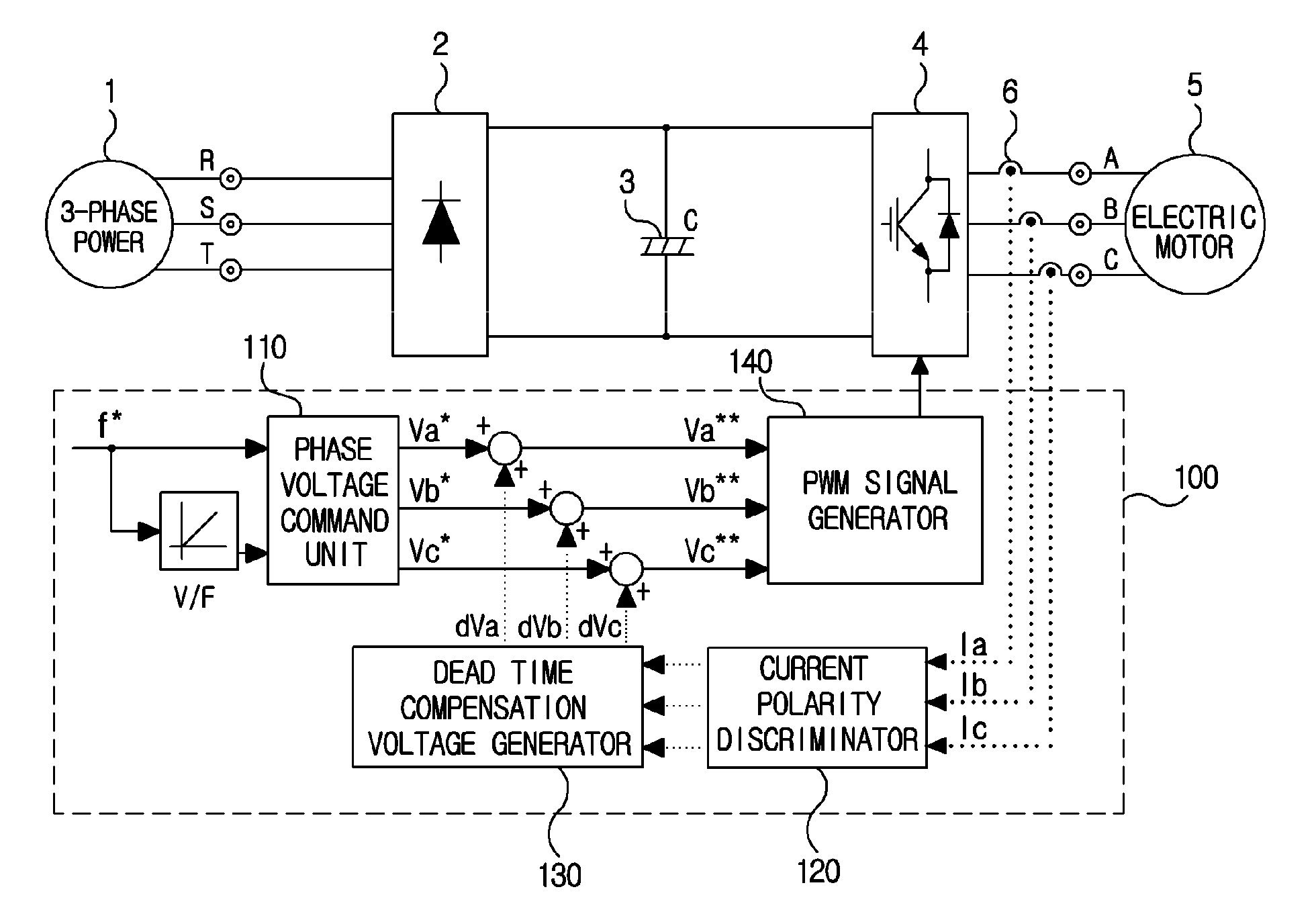
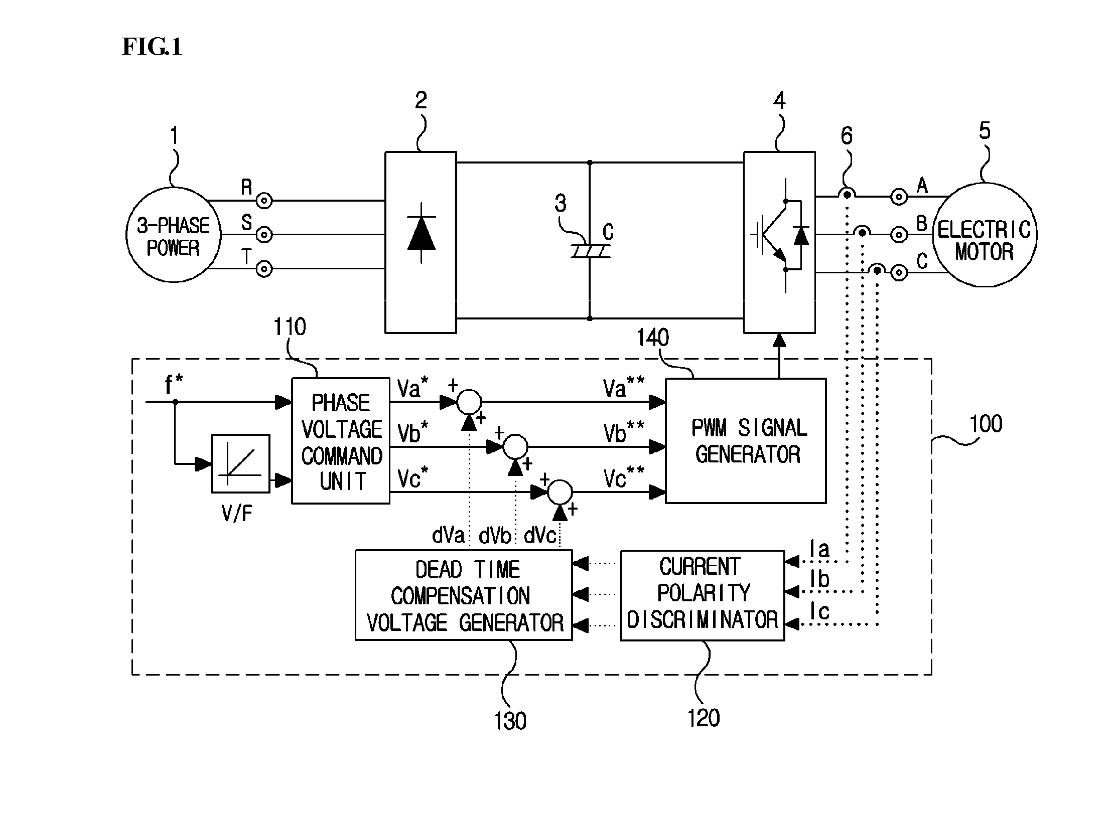
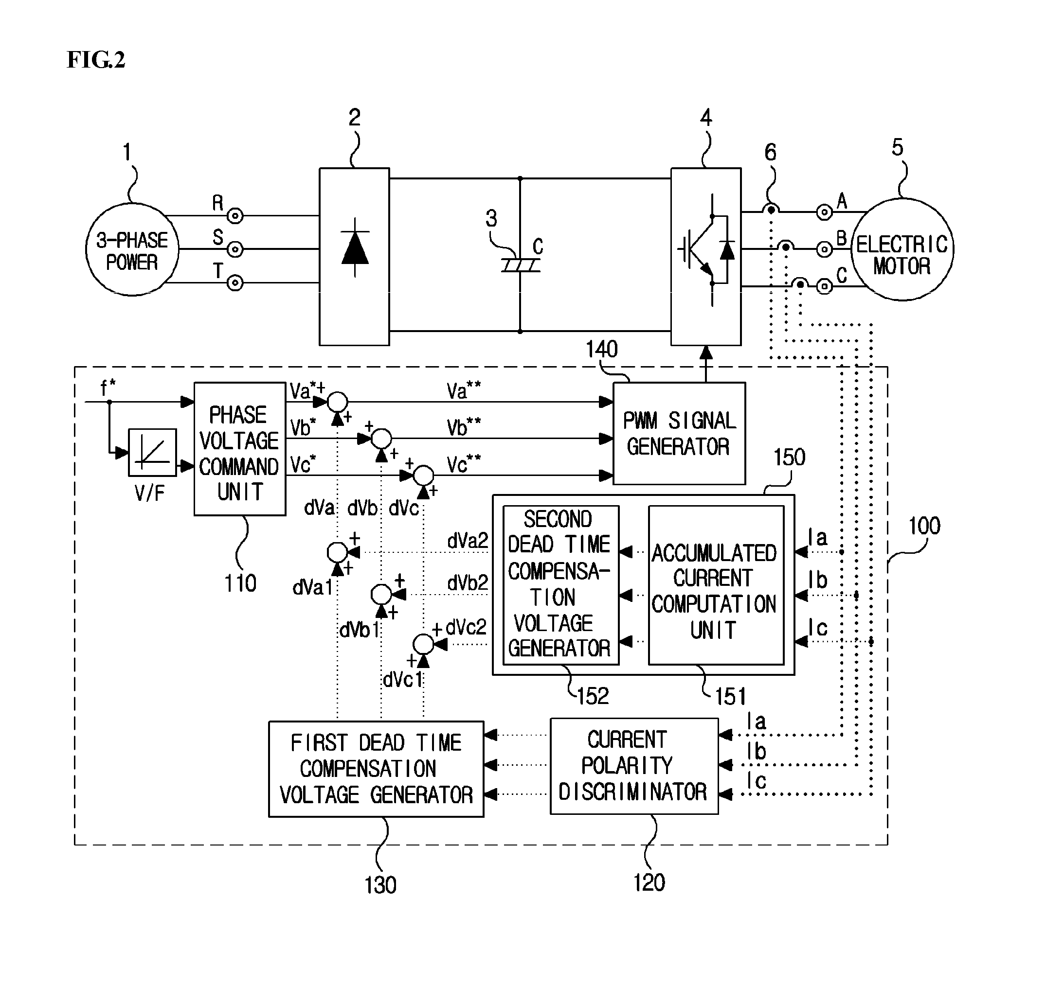
An output current distortion compensating apparatus in an inverter is disclosed, the inverter including an inverter controller generating a PWM signal for controlling a PWM voltage generator, wherein the inverter controller includes a first dead time compensation voltage generator generating a compensation voltage based on an output current polarity of each phase in the inverter, and a second dead time compensation voltage generator generating a compensation voltage based on an output current waveform of each phase in the inverter, and wherein a first dead time compensation voltage outputted from the first dead time compensation voltage generator and a second dead time compensation voltage outputted from the second dead time compensation voltage generator are added to generate a final dead time compensation voltage, thereby preventing occurrence of hunting phenomenon in which a current is greatly fluctuated.

Description

CROSS-REFERENCE TO RELATED APPLICATION[0001]The present application is based on, and claims priority from, Korean Application Numbers 10-2010-0042657, filed May 6, 2010, the disclosure of which is incorporated by reference herein in its entirety.BACKGROUND OF THE INVENTION[0002]1. Field of the Invention[0003]The present disclosure relates to an output current distortion compensating apparatus in an inverter, and more particularly to an output current distortion compensating apparatus in an inverter configured to prevent an output current distortion in an inverter by generating an additional compensation voltage to cope with a distortion phenomenon of an output current caused by an error in a dead time compensation voltage.[0004]2. Description of Related Art[0005]An inverter for motor driving can be used for various purposes. Examples of the inverter for driving a motor may include industrial manufacturing facilities, building air conditioners and elevators. A conventional 3-phase in...

Claims


Application Information

Patent Timeline
Patent Type & Authority Applications(United States)
IPC IPC(8): H02M1/12H02M7/48
CPCH02M7/5387H02M1/12H02M7/48H02P27/04
Inventor KIM, KWANG YEON
Owner LSIS CO LTD
Learn More