
Handover method supporting terminal mobility

a terminal and mobility technology, applied in the field of wireless communication technologies, can solve the problems of inability to ensure the success of handover, excessive signaling resources and wireless resources, and excessive handover, so as to reduce wasted signaling resources and wireless resources, and improve the quality of service

Active Publication Date: 2011-11-10
SAMSUNG ELECTRONICS CO LTD
View PDF3 Cites 68 Cited by
  • Summary
  • Abstract
  • Description
  • Claims
  • Application Information

AI Technical Summary

Benefits of technology

[0020]An aspect of the present invention is to address at least the above-mentioned problems and / or disadvantages and to provide at least the advantages described below. Accordingly, an aspect of the present invention is to provide a handover method that supports terminal mobility, so as to reduce wasted signaling resources and wireless resources during the Selected IP Traffic Offload (SIPTO) and Local IP Access (LIPA) handover or to make the User Equipment (UE) use the optimal bearer as far as possible after the handover, so that the Quality of Service (QoS) is improved.
[0022]Still another aspect of the present invention is to provide a handover method that supports terminal mobility, wherein during a handover from a source base station to a target base station by UE, if the handover is performed as an S1 interface handover, where an S1 interface is an interface between the base station and a core network, the method including providing, by a target core network node, access control determination information for the target base station, and, if the target base station permits a bearer supporting an SIPTO or LIPA service to perform the handover according to the access control determination information, notifying the target core network node to update bearer information, or otherwise, notifying handover failure to the target core network node with respect to the bearer not allowed to perform the handover, or alternatively, notifying the target core network node to, during the handover to a target network by the UE or after the handover to the target network, perform bearer release or deactivation for the bearer not allowed to perform the handover.

Problems solved by technology

First, a successful handover cannot be ensured when the handover is performed.
Or, when the UE performs the handover from an enterprise network to another network, the UE is not allowed to have such a handover, which may cause handover failure.
Such a manner can occupy excessive signaling resources and wireless resources.
Second, when the handover is performed, although the handover can be successful, an optimal bearer cannot be ensured after the handover.
Although the policy of the operator allows having the handover, the bearer after the handover might not be the optimal bearer, which may cause network resources to not be used optimally.

Method used


Image

  • Handover method supporting terminal mobility
  • Handover method supporting terminal mobility
  • Handover method supporting terminal mobility

Examples


first exemplary embodiment

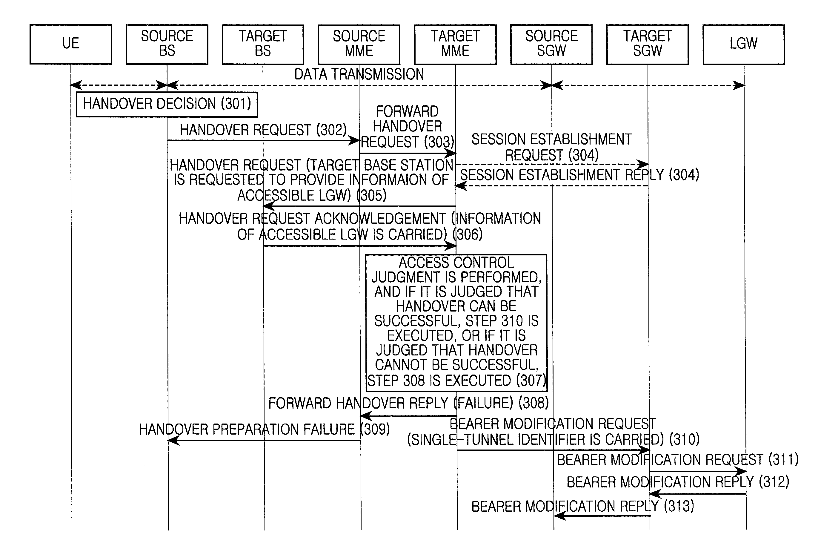
[0063]FIG. 3 is a flowchart illustrating a method according to a first exemplary embodiment of the present invention. Referring to FIG. 3, the method can include the following steps.

[0064]At step 301, the source base station decides to perform the handover.

[0065]At step 302, the source base station sends a handover request to a source Mobile Management Entity (MME). In the handover request, target base station information, e.g., a target base station identification (ID) and target Tracking Area ID (TAI), is included, and information such as a target CSG or a handover type and the like can also be included.

[0066]At step 303, the source MME sends a forward handover request to a target MME. The target base station information, e.g., an evolved Node B (eNB) ID that can differentiate whether the target base station is a Home enhance Node B (HeNB) or a macro base station, is included in the forward handover request. In addition, the information such as the target TAI, target Closed Subscr...

second exemplary embodiment

[0092]FIG. 4 is a flowchart illustrating the method according to a second exemplary embodiment of the present invention. Referring to FIG. 4, the method can include the following steps.

[0093]Steps 401 to 404 are the same as steps 301 to 304 in the first exemplary embodiment, and a repeated description thereof is omitted herein.

[0094]At step 405, the target MME sends the handover request to the target base station. The information of the LGW currently accessed by the source base station is included in the handover request.

[0095]Specifically, the information of the LGW currently accessed by the source base station can be the identifier of the currently accessed LGW, the IP address of the LGW or the domain name information of the LGW, etc.

[0096]The target MME knows that the currently accessed UE supports the SIPTO or the LIPA according to the information in the received forward handover request message. The target MME decides also to establish the direct tunnel in the target system, an...

third exemplary embodiment

[0106]FIG. 5 is a flow chart illustrating the method according to a third exemplary embodiment of the present invention. Referring to FIG. 5, the method can include the following steps.

[0107]Steps 501 to 502 are the same as Steps 301 to 302 in the first embodiment, and a repeated description thereof is omitted herein.

[0108]At step 503, the source MME requests the target base station to provide the information of the LGW accessible to the target base station according to the target base station information in the handover request.

[0109]A new S1 interface Application Protocol (S1-AP) message is added to request the information of the LGW accessible to the target base station.

[0110]At step 504, the target base station replies to the source MME with the information of the LGW accessible to the target base station.

[0111]Likewise, a new S1-AP message can also be added in this step to request the information of the LGW accessible to the target base station.

[0112]Specifically, the informati...


PUM


Abstract

A handover method for supporting terminal mobility is provided. Before a target core network node updates bearer information according to a target base station to which a User Equipment (UE) performs the handover, an access control determination procedure is added. According to the access control determination information provided by the target base station, if it is determined that the bearer supporting a Selected Internet Protocol (IP) Traffic Offload (SIPTO) or Local IP Access (LIPA) service is permitted to perform the handover, the target core network node updates the bearer information. If it is determined that the bearer supporting the SIPTO or LIPA service is not allowed to perform the handover, the handover failure is notified with respect to the bearer not allowed to perform the handover, and the bearer information is not updated, thus the wasted signaling resource and wireless resource are reduced. Alternatively, during the handover to the target network by the UE or after the handover to the target network, the bearer release or deactivation is performed for the bearer not allowed to perform the handover, so that the UE can re-initiate the bearer establishment process with respect to the bearer not allowed to perform the handover, thus an optimized bearer is established and the Quality of Service (QoS) is ensured.

Description

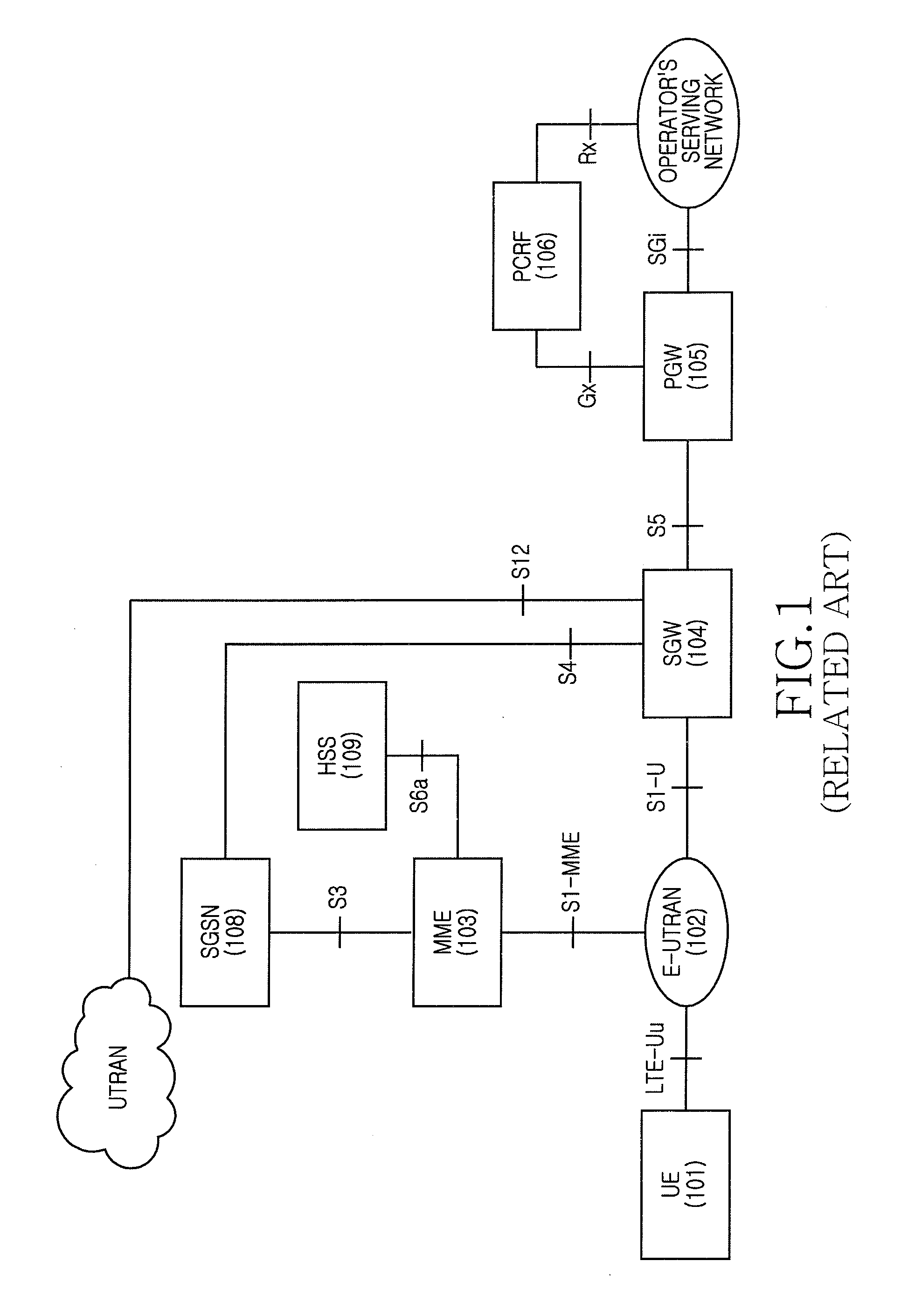
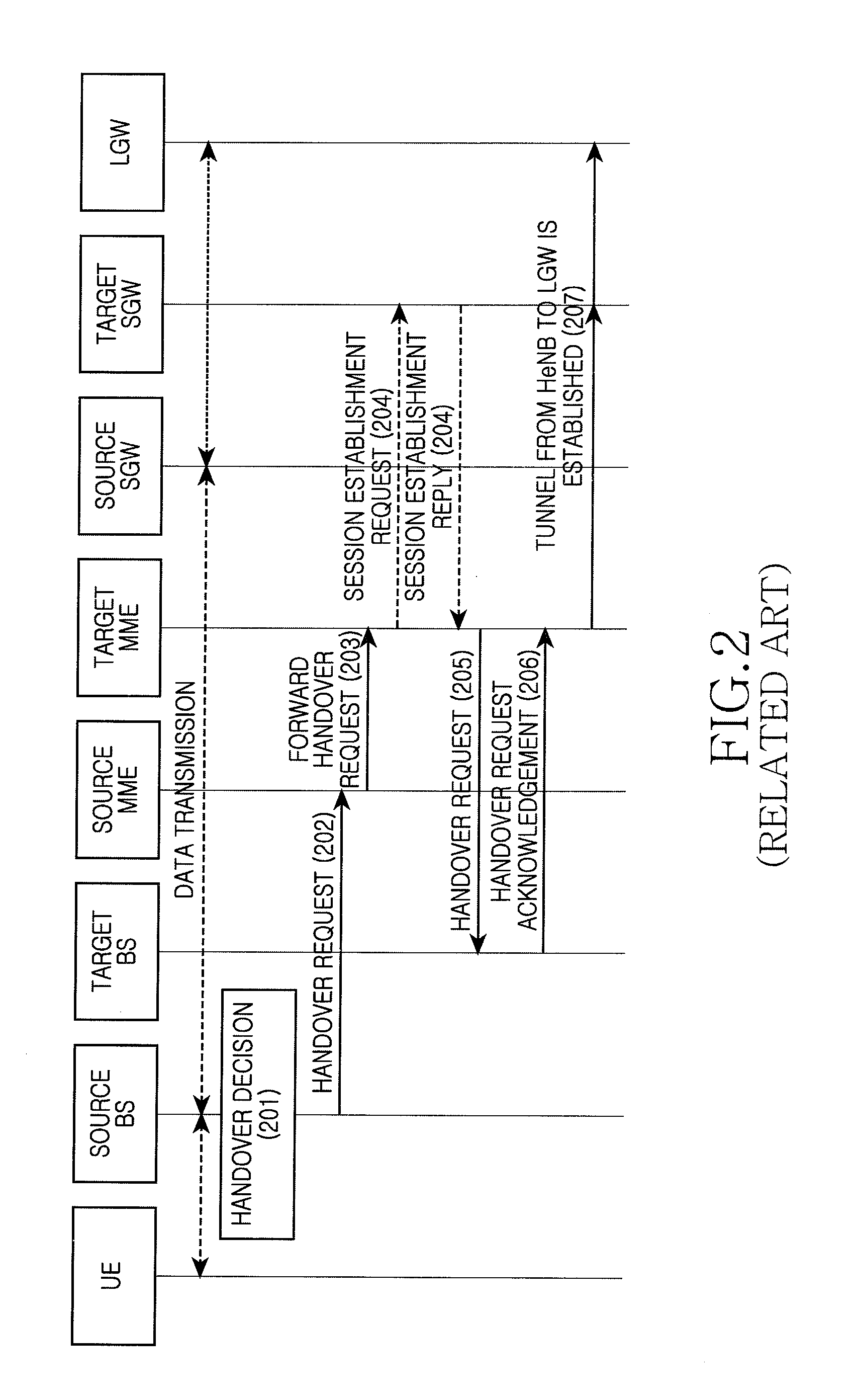
PRIORITY[0001]This application claims the benefit under 35 U.S.C. §119(a) of a Chinese patent application filed on May 10, 2010 in the Chinese Intellectual Property Office and assigned Serial No. 201010175987.2, and a Chinese patent application filed on Jul. 20, 2010 in the Chinese Intellectual Property Office and assigned Serial No. 201010234849.7, the entire disclosures of which are hereby incorporated by reference.BACKGROUND OF THE INVENTION[0002]1. Field of the Invention[0003]The present invention relates to wireless communication technologies. More particularly, the present invention relates to a handover method that supports terminal mobility.[0004]2. Background of the Invention[0005]FIG. 1 is a diagram illustrating a System Architecture Evolution (SAE) system architecture of the related art. Specifically, User Equipment (UE) 101 is a terminal device for receiving data. An Evolved Universal Terrestrial Radio Access Network (E-UTRAN) 102 is a wireless access network, in which a...

Claims


Application Information

Patent Timeline
Patent Type & Authority Applications(United States)
IPC IPC(8): H04W36/00
CPCH04W28/04H04W28/06H04W76/064H04W72/00H04W76/028H04W36/08H04W8/082H04W48/02H04W76/19H04W76/34
Inventor LIANG, HUARUIWANG, HONGXU, LIXIANG
Owner SAMSUNG ELECTRONICS CO LTD
Learn More