Fiber-Optic Vibration Sensor

a fiber-optic, vibration sensor technology, applied in the direction of instruments, measurement devices, using wave/particle radiation means, etc., can solve the problems of destroying the generator, affecting the operation of the generator, so as to achieve the greatest possible fiber length, simplify the design of the vibration sensor, and the effect of high sensitivity

Active Publication Date: 2011-11-10
SIEMENS ENERGY GLOBAL GMBH & CO KG
View PDF3 Cites 17 Cited by
  • Summary
  • Abstract
  • Description
  • Claims
  • Application Information

AI Technical Summary

Benefits of technology

[0007]According to the invention only the net weight of the fiber itself is used as the centrifugal mass. In other words, in contrast to known sensors of this type, no additional centrifugal mass is attached at the end of the fiber. This considerably simplifies the design of the vibration sensor.
[0008]In order to keep the resonant frequency sufficiently high relative to the operating frequency, typically 400 Hz, the chosen length of the fiber should beneficially be short enough. For high sensitivity, on the other hand, the greatest possible fiber length is advantageous.
[0010]According to an advantageous embodiment of the invention an 8° break of the end surface is used in order to avoid back-reflections at the terminating surface of the optical fiber. The azimuthal orientation of the fiber end relative to the mirror is beneficially chosen such that the break and the mirror surface include the maximum possible angle. In other words, break and mirror surface form a “V” shape. The oblique terminating surface causes the light to be refracted slightly downward—downward with reference to the shape of the “V”—out of the fiber, by approx. 3.5°. The effective angle of incidence onto the mirror is reduced as a result.

Problems solved by technology

Damage to the insulation or, as the case may be, to the copper can occur at excessively high amplitudes of the bar oscillations.
The damage can result in the destruction of the generator.

Method used


Image

  • Fiber-Optic Vibration Sensor
  • Fiber-Optic Vibration Sensor

Examples


Embodiment Construction

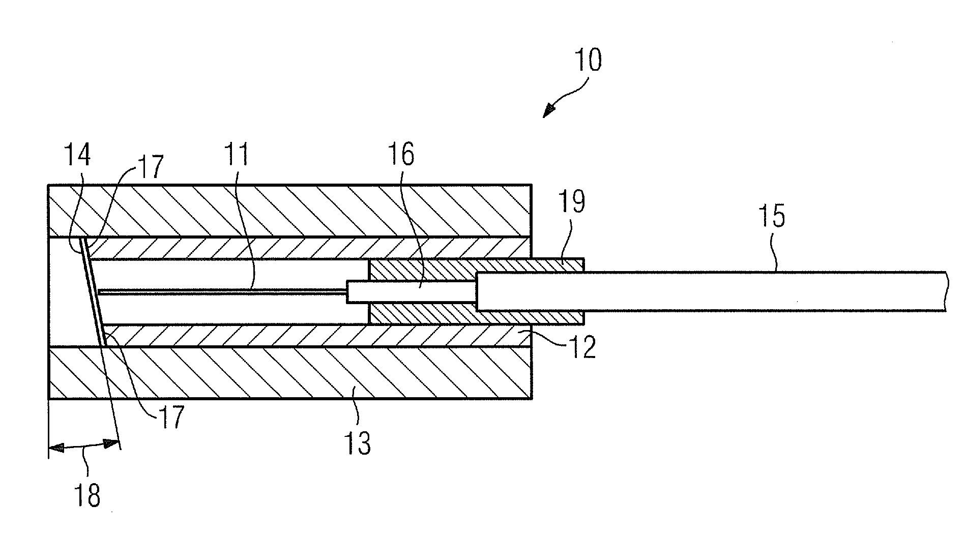
[0017]The fiber-optic vibration sensor 10 shown in FIG. 1 includes as an essential element a glass fiber 11. This is embodied as a multimode fiber 62 / 125 μm. A 16 mm-long section of the glass fiber 11 is freestanding. The glass fiber 11 ends at the end of said section. Immediately after the freestanding section the glass fiber 11 is fixed in a guide element 16. Further on from this the glass fiber 11 is routed loosely in a 3.7 mm-diameter Teflon tube 15.

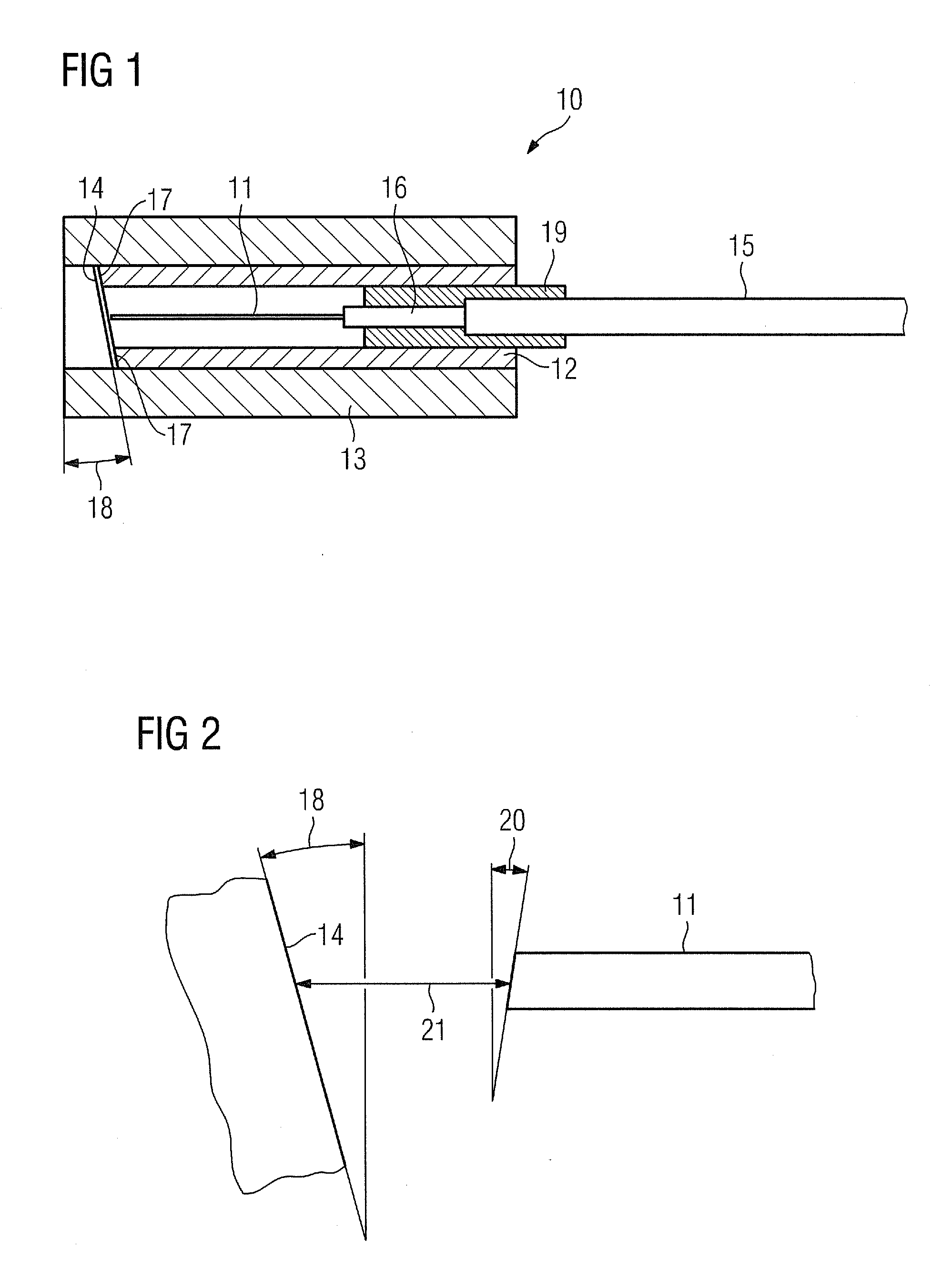
[0018]The end of the Teflon tube 15 is enclosed together with the guide element 16 by a first sheath 19. A second sheath 12 is provided around the first sheath 19. The second sheath 12 extends from the region of the first sheath beyond the freestanding section of the glass fiber 11. On the end face, i.e. at the point where the glass fiber 11 ends, the second sheath 12 is terminated with an end beveled at an angle of 11°, which in the case of the cylinder-shaped second sheath 12 reveals itself in a circular-ring-shaped, beveled end 17...


PUM


Abstract

A fiber-optic vibration sensor for generators in power stations is disclosed. The sensor includes an optical fiber which has a freestanding end, wherein the freestanding end is caused to oscillate under the influence of vibrations, and the resulting oscillations are detected as a measure for the vibrations. Only the net weight of the optical fiber serves as a centrifugal mass.

Description

CROSS REFERENCE TO RELATED APPLICATIONS[0001]This application claims priority of European Patent Office application No. 10 2010 019 813.7 DE filed May 6, 2010, which is incorporated by reference herein in its entirety.FIELD OF INVENTION[0002]The invention relates to a fiber-optic vibration sensor, in particular for use in a generator.BACKGROUND OF INVENTION[0003]Generators in the power station field exhibit oscillations at double the line frequency in the region of the end-windings, inter alia. Damage to the insulation or, as the case may be, to the copper can occur at excessively high amplitudes of the bar oscillations. The damage can result in the destruction of the generator. Since the end-windings are at high-voltage potential, fiber-optic acceleration sensors (so-called FOAs=Fiber Optic Accelerometers) are increasingly used for monitoring such oscillations. An example of such an FOA operates with a centrifugal mass which is connected to an optical fiber and which is deflected b...

Claims


Application Information

Patent Timeline
Patent Type & Authority Applications(United States)
IPC IPC(8): G02B6/00
CPCG01H9/004
Inventor BOSSELMANN, THOMASVILLNOW, MICHAELWILLSCH, MICHAEL
Owner SIEMENS ENERGY GLOBAL GMBH & CO KG
Why Eureka
Try Eureka