Double Threaded Orthopedic Screw

Inactive Publication Date: 2011-11-10
MAZOR ROBOTICS
View PDF6 Cites 28 Cited by
  • Summary
  • Abstract
  • Description
  • Claims
  • Application Information

AI Technical Summary

Benefits of technology

[0019]Although the screws described in this application have been described generally in relation to spinal fusion procedures, it is to be understood that this application is not meant to be limited to such cases but that the screws described and claimed could be used in any orthopedic procedure where

Problems solved by technology

However, for the spinal fusion procedures, maximum screw diameter is limited by the 5-8 mm pedicle wa

Method used


Image

  • Double Threaded Orthopedic Screw
  • Double Threaded Orthopedic Screw
  • Double Threaded Orthopedic Screw

Examples


Example

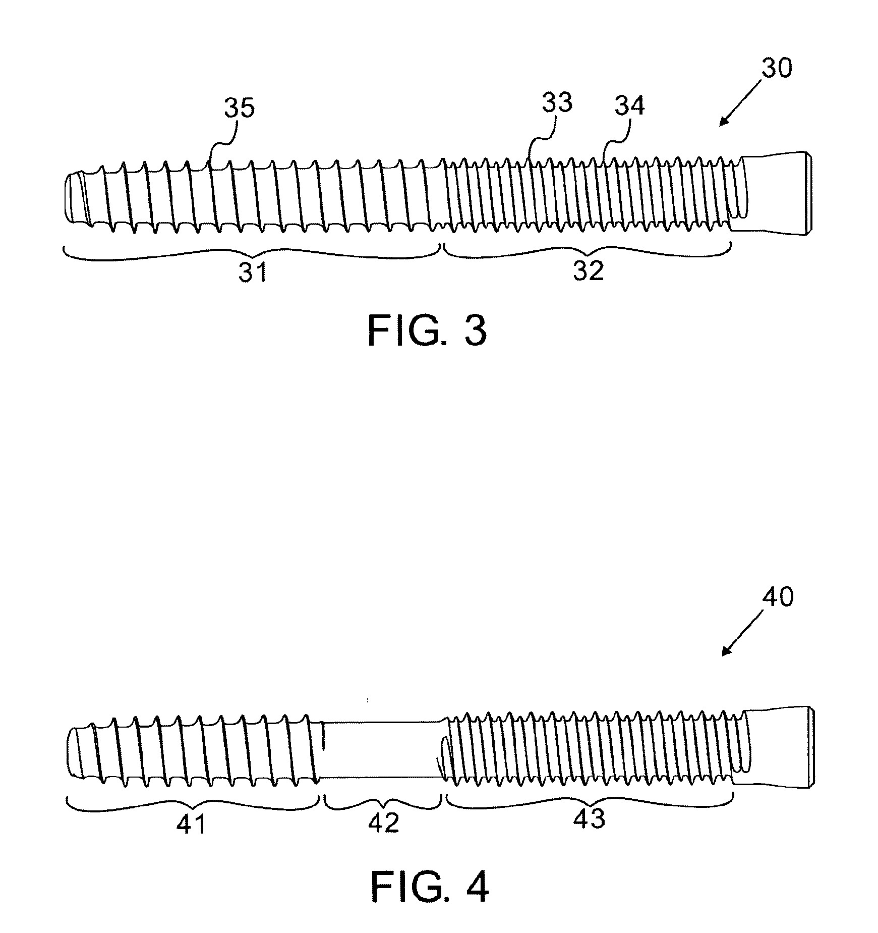
[0027]Reference is now made to FIG. 3, which illustrates schematically a bone screw 30 according to a first implementation of the screws described in this application. The thread of the screw has two distinct parts, a distal part 31 and a proximal part 32, each having a different thread configuration:

(i) a thread 35 at the distal end, optimally sized and pitched for entry and fixation in cancellous bone, and

(ii) a double thread configuration at the proximal end 32, for entry and fixation in cortical bone, with two threads having different outer diameters, a larger 33 and a smaller 34 outer diameter.

[0028]In this proximal section, the larger, outer diameter thread 33:

(a) has the same pitch as the pitch of the cancellous thread 35 of the distal section,

(b) has an outer diameter which is generally the same or slightly larger, but not less than that of the cancellous thread 35 of the distal section, and

(c) is formed on the same helix as that of the cancellous thread 35 of the distal sec...


PUM


Abstract

An orthopedic screw having a thread with two parts, a distal and a proximal part, each having a different thread configuration. The distal section has a thread with outer dimension and pitch suitable for entry into cancellous bone, while the proximal section has a composite thread comprising (i) a first thread of the same or slightly larger outer diameter as the cancellous thread in the distal section, having the same pitch thereof, and lying on the same helix, and (ii) another thread having a smaller outer diameter but the same pitch as the first thread, but disposed on a helix displaced from that of the first thread, such that it lies between the crests of the first thread. This screw enables optimum fixation strength in a bone or bones having a harder cortical outer section and a softer cancellous inner section. The screw may have an unthreaded central section.

Description

FIELD OF THE INVENTION[0001]The present invention relates to the field of orthopedic screws for use in joining bones, especially for use in situations where two types of bone need to be penetrated and joined.BACKGROUND OF THE INVENTION[0002]A common treatment for spinal stabilization is the fixation of two or more vertebrae performed by insertion of a pair of screws into each of the vertebrae to be fused and connecting the screws heads on either side of the spine by two rigid rods. Cleaning the disc space and inserting bone graft into the cleaned disc space causes bone to grow between the vertebrae until, several months later, the fusion is completed.[0003]The screws are usually inserted into the pedicles, two for each vertebra such that a minimum of four screws are required for each level of fusion. Reference is now made in FIG. 1 which is a cross-sectional axial view of a vertebra 10, showing a pair of pedicle screws 11 passing from the pedicles 12 into the vertebral body 13, and ...

Claims


Application Information

Patent Timeline
IPC IPC(8): A61B17/88A61B17/86
CPCA61B17/863A61B17/70
Inventor BAR, YOSSEFZEHAVI, ELIHEWKO, BRIANSHOHAM, MOSHE
Owner MAZOR ROBOTICS
Why Eureka
Try Eureka