Energy efficient lighting system

a lighting system and energy-saving technology, applied in the direction of process and machine control, material dimension control, instruments, etc., can solve the problems of complex and expensive existing control systems, and achieve the effect of reducing power consumption

Inactive Publication Date: 2011-11-10
GREEN BALLAST
View PDF27 Cites 34 Cited by
  • Summary
  • Abstract
  • Description
  • Claims
  • Application Information

AI Technical Summary

Benefits of technology

[0005]The present invention relates generally to an energy efficient lighting system. More specifically, a preferred embodiment of the present invention relates to a system and method for controlling the individual power consumption and light output of each lighting luminary at a local level based upon a multitude of inputs whereby at least one of the inputs preferably is from building central control or command. The lighting system preferably has one or more lighting fixtures, each lighting fixture preferably independently controlled at the lighting fixture. Preferably, a microcontroller in a microcontroller circuit is operatively associated with, proximate to and preferably in the housing of the lighting fixture with the lamps and processes all input signals from sensors and other control devices, and determines the power output to, and hence the amount of lighting provided by the lamps and lighting fixture. The microcontroller or microprocessor may be in a housing module separate from the light fixture housing (with the lamps). Preferably the input signals from the sensors and other control inputs are processed at the local level by the microcontroller, and independent of the other lighting fixtures, to use the lowest power consumption. The microcontroller preferably receives all the control signal inputs and filters or otherwise processes them to permit the input signal that provides for the lowest power level output to the lamps to control the operation of the lamp driving circuit.

Problems solved by technology

These existing control systems however are complex and expensive.

Method used


Image

  • Energy efficient lighting system
  • Energy efficient lighting system
  • Energy efficient lighting system

Examples


Embodiment Construction

[0034]Referring now to the various figures of the drawings, a preferred embodiment of the lighting system of the present invention shall be described in detail, where like numerals shall refer to like parts.

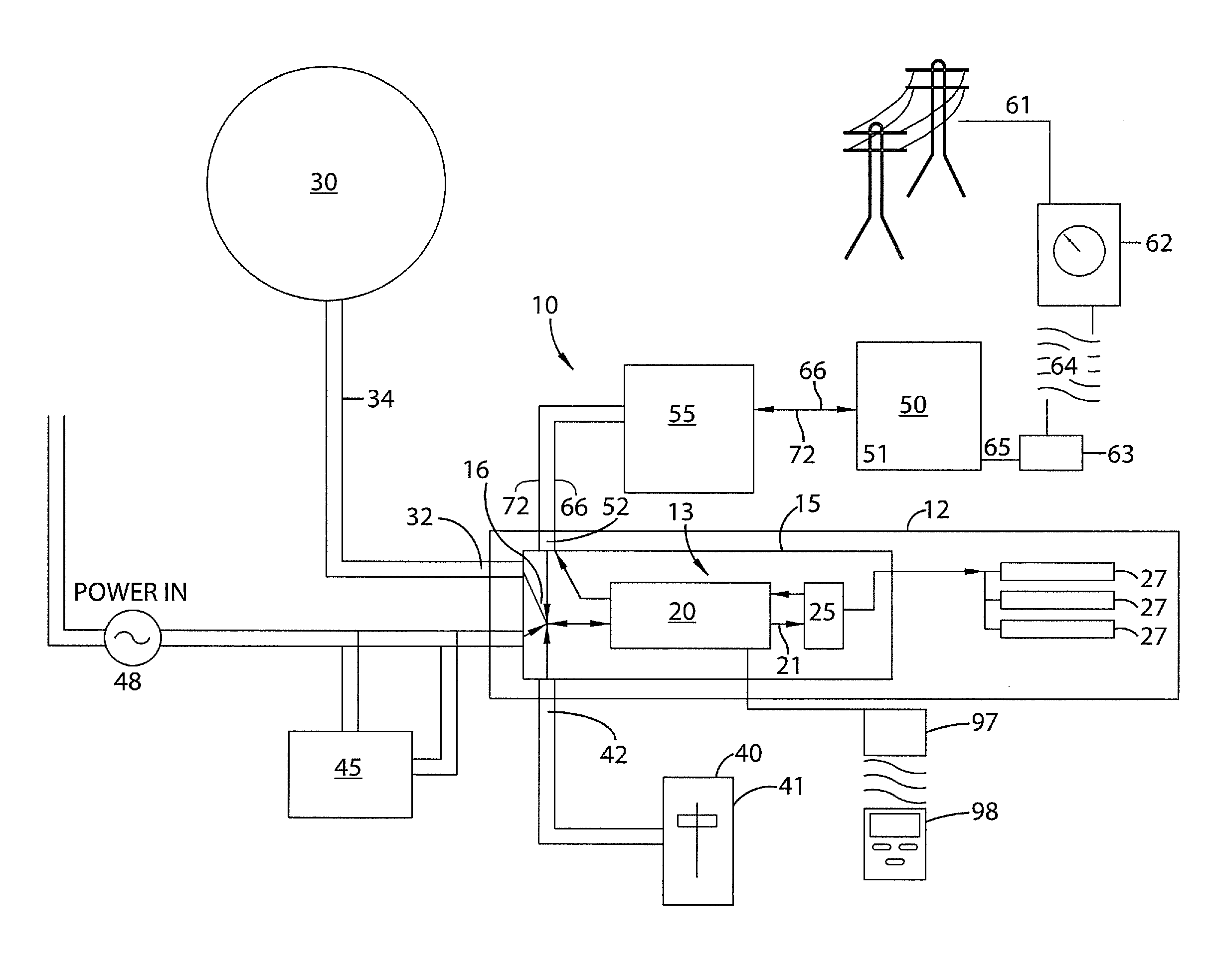
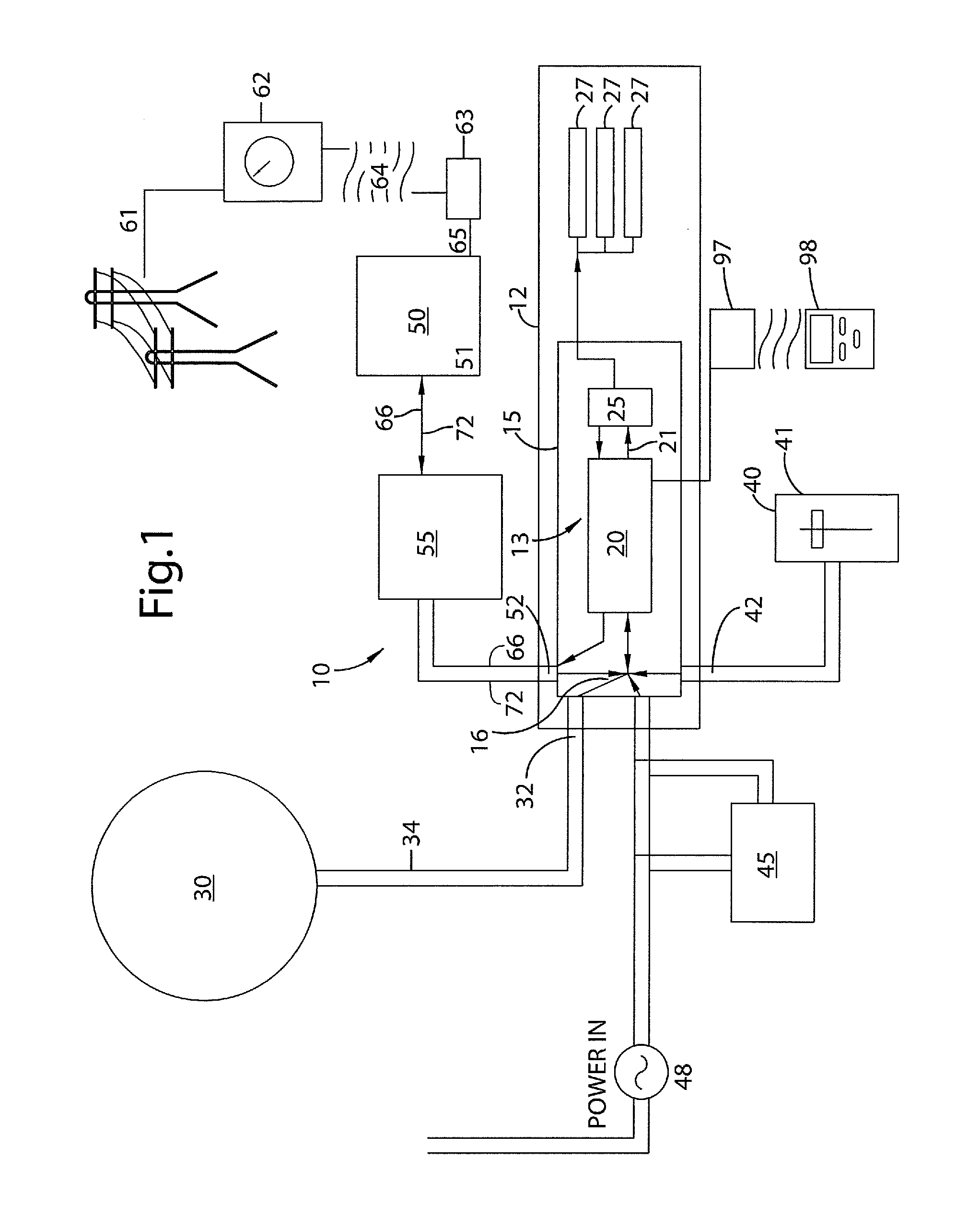
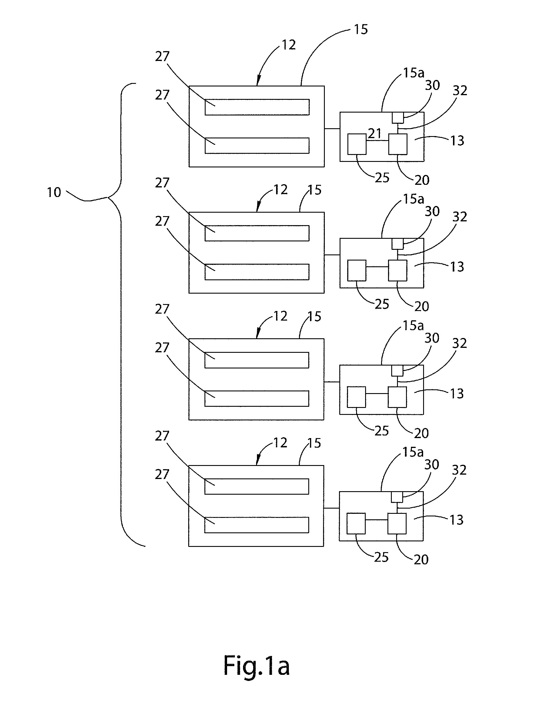
[0035]FIG. 1 shows a block diagram representation of the lighting system 10 having a lighting fixture or luminary 12. While FIG. 1 illustrates only one lighting fixture 12, lighting system 10 typically has a plurality of lighting fixtures 12. The lighting fixture 12 has one or more lamps or bulbs 27, a circuit housing 15, control circuitry 13 and a number of control inputs 16. The circuit housing 15 preferably houses the control circuitry 13 which may include microcontroller circuitry 20 including one or more microcontroller central processor(s) 20a (and associated circuitry), and one or more lamp driving circuit(s) 25 for powering or driving one or more lamps 27. While the description has used the terms lighting fixtures, luminaries, lamps, and / or bulbs, it should be understood ...


PUM


Abstract

The present invention relates to an energy efficient lighting system, more particularly a system and method for controlling the individual power consumption and light output for each lighting luminary at a local level based upon a multitude of inputs whereby at least one of the inputs preferably is from central building control. Preferably, the ballast or lighting fixture is operatively associated with and preferably includes a microcontroller that processes all signals from sensors and other control devices including a building central control sensor that manages building power consumption and selects the most energy efficient input signal to power the lamps. The lighting system preferably includes a plurality of lighting fixtures and the lighting output of each fixture is determined on the local level by the microcontroller associated with and preferably in each circuit housing or ballast associated with the fixture.

Description

CROSS REFERENCE TO RELATED APPLICATION[0001]This application claims the benefit of U.S. Provisional Application No. 61 / 331,379 filed May 4, 2010, the entire content of which is incorporated herein by reference thereto.FIELD OF THE INVENTION[0002]The present invention relates to an energy efficient lighting system, more particularly a system and method for controlling the individual power consumption and light output for each lighting luminary at a local level based upon a multitude of inputs preferably whereby at least one of the inputs preferably is from central building control.BACKGROUND OF THE INVENTION[0003]Energy conservation and management in large buildings is very important. In many buildings, control and monitoring of lighting systems is performed by a central building command or control. The central building command, which operates the lighting system, is often located remotely from the individual lighting fixtures or luminaries, and may even be located off-site from the ...

Claims


Application Information

Patent Timeline
Patent Type & Authority Applications(United States)
IPC IPC(8): G06F1/32
CPCH05B37/029H05B37/0218H05B37/0281H05B37/0272H05B37/0263H05B47/185H05B47/16H05B47/155H05B47/11H05B47/19H05B47/195Y02B20/40
Inventor BOWMAN, BRIAN T.ERICKSON, JAMES A.
Owner GREEN BALLAST
Why Eureka
Try Eureka