Multi-electrode system with vibrating electrodes

a multi-electrode and electrode technology, applied in the field of fiber optics, can solve the problems of destabilization and extinguishing plasma, and achieve the effects of reducing electrode oxidation, enhancing the isothermic range of plasma field, and enhancing the isothermic stability of plasma field

Active Publication Date: 2011-11-17
3SAE TECH
View PDF4 Cites 6 Cited by
  • Summary
  • Abstract
  • Description
  • Claims
  • Application Information

AI Technical Summary

Benefits of technology

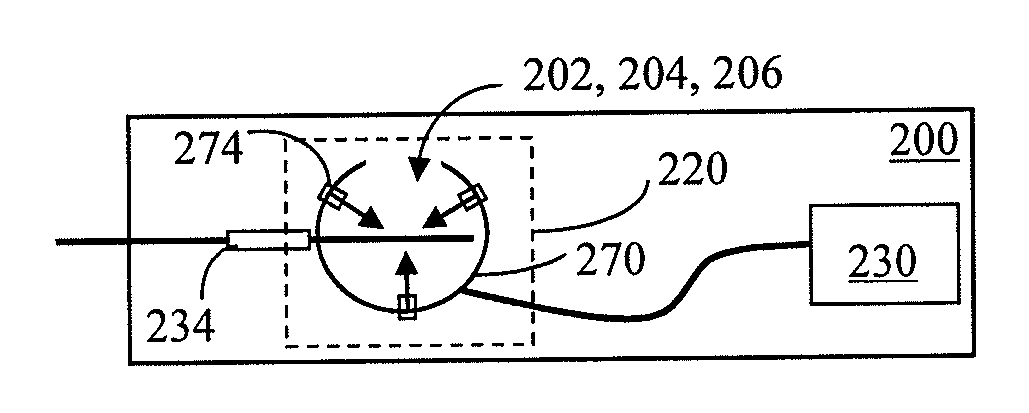
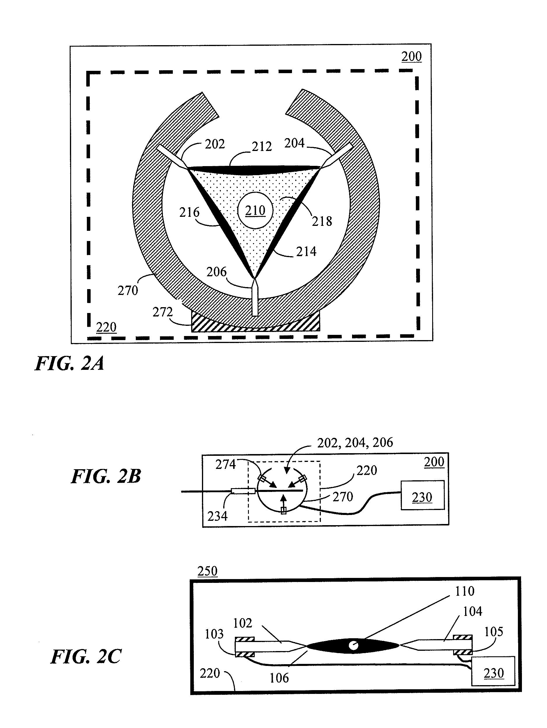
[0013]In accordance the present invention, a multi-electrode system can be a three phase system configured to operate in ambient conditions, or in a partial or complete vacuum, with vibration or isolation of one or more of the multiple electrodes. There are several benefits of such systems and methods. For example, such systems and methods, when provided in a partial or complete vacuum, provide enhanced isothermic stability of the plasma field due to the elimination (or reduction) of convection. Compare to conventional systems and methods, where as heat from the plasma rises (at atmospheric pressure) a turbulent upward breeze is created that can disturb the plasma and alter the thermal balance of the plasma or slightly alter the location of the section of the fiber being heated.
[0014]Also such systems and methods, when provided in a partial or complete vacuum, provide enhanced isothermic range of the plasma field due to the elimination (or reduction) of convection. Compare to conventional systems and methods, where as heat from the plasma rises (at atmospheric pressure) it creates a turbulent upward breeze that can disturb the ion trail between the electrodes. This disruption will destabilize and extinguish a plasma in air that is otherwise completely stable in a vacuum or partial vacuum. Since air is an insulator, the dielectric between the electrodes is substantially reduced in a vacuum or partial vacuum. This dielectric reduction allows for an arc to be initiated and maintained at power levels far below what is achievable in air.
[0015]Also such systems and methods, when provided in a partial or complete vacuum, provide reduced electrode oxidation. By reducing the oxygen levels present during plasma generation the electrodes will deteriorate at a substantially slower rate.
[0016]Also such systems and methods, when provided in a partial or complete vacuum, provide elimination of combustion. Some fiber coatings such as acrylate (the most common fiber coating) are combustible in air at atmospheric pressures and can burn if exposed to a standard arc. When the same process is implemented in a vacuum or partial vacuum the lack of oxygen prevents combustion of the coating allowing it to be thermally ablated (a process similar to “burst technology”).
[0020]The vibration mechanism can broaden a width of the heated field to a full, half max of a Gaussian thermal profile.
[0043]Vibrating the at least one electrode can broaden a width of the heated field to a full, half max of a Gaussian thermal profile.

Problems solved by technology

This disruption will destabilize and extinguish a plasma in air that is otherwise completely stable in a vacuum or partial vacuum.

Method used


Image

  • Multi-electrode system with vibrating electrodes
  • Multi-electrode system with vibrating electrodes
  • Multi-electrode system with vibrating electrodes

Examples


Embodiment Construction

[0065]It will be understood that, although the terms first, second, etc. can be used herein to describe various elements, these elements should not be limited by these terms. These terms are used to distinguish one element from another, but not to imply a required sequence of elements. For example, a first element can be termed a second element, and, similarly, a second element can be termed a first element, without departing from the scope of the present invention. As used herein, the term “and / or” includes any and all combinations of one or more of the associated listed items.

[0066]It will be understood that when an element is referred to as being “on” or “connected” or “coupled” to another element, it can be directly on or connected or coupled to the other element or intervening elements can be present. In contrast, when an element is referred to as being “directly on” or “directly connected” or “directly coupled” to another element, there are no intervening elements present. Oth...


PUM

PropertyMeasurementUnit
initiating voltageaaaaaaaaaa
diameteraaaaaaaaaa
diameteraaaaaaaaaa

Abstract

A multi-electrode system includes a fiber holder that holds at least one optical fiber, a plurality of electrodes arranged to generate a heated field to heat the at least one optical fiber, and a vibration mechanism that causes at least one of the electrodes from the plurality of electrodes to vibrate. The electrodes can be disposed in at least a partial vacuum. The system can be used for processing many types of fibers, such processing including, as examples, stripping, splicing, annealing, tapering, and so on. Corresponding fiber processing methods are also provided.

Description

CROSS REFERENCES TO RELATED APPLICATIONS[0001]This application is a continuation application of U.S. non-provisional patent application Ser. No. 12 / 688,489, filed Jan. 15, 2010, entitled Multi-Electrode System with Vibrating Electrodes, which is a continuation-in-part application of U.S. non-provisional patent application Ser. No. 12 / 027,394 filed Feb. 7, 2008, now U.S. Pat. No. 7,670,065, issued on Mar. 2, 2010, entitled Multi-Electrode System, which claimed priority under 35 U.S.C. §119(e) from co-pending, commonly owned U.S. provisional patent application Ser. No. 60 / 976,859 filed Oct. 2, 2007, entitled Multi-Electrode System In A Vacuum, U.S. provisional patent application Ser. No. 60 / 953,803 filed Aug. 3, 2007, entitled Three-phase Arc for Fiber Splicing and Improved Fiber Stripping, and U.S. provisional patent application Ser. No. 60 / 888,691 filed Feb. 7, 2007, entitled Three-Phase Arc for Large Diameter Fiber Splicing and Improved Fiber Stripping, the disclosure of each of wh...

Claims


Application Information

Patent Timeline
Patent Type & Authority Applications(United States)
IPC IPC(8): G02B6/255C03B37/12
CPCG02B6/245G02B6/262G02B6/2553G02B6/2551C03B25/02C03B37/15C03C25/002G02B6/2556
Inventor WILEY, ROBERT G.CLARK, BRETTMEITZLER, JARED C.TROUTMAN, CLYDE J.
Owner 3SAE TECH
Why Eureka
Try Eureka