Parking lock device for an automatic transmission of a motor vehicle

a technology for automatic transmission and locking device, which is applied in the direction of gearing control, clutches, gearing elements, etc., can solve problems such as spark formation, and achieve the effect of increasing safety

Active Publication Date: 2011-11-17
ZF FRIEDRICHSHAFEN AG
View PDF1 Cites 10 Cited by
  • Summary
  • Abstract
  • Description
  • Claims
  • Application Information

AI Technical Summary

Benefits of technology

[0006]The purpose of the present invention, based on a parking lock device of the type mentioned at the start, is to increase safety when engaging the parking lock.
[0007]According to the invention, it is provided that the locking pawl is guided laterally by a low-friction supporting element. This has the advantage that when the parking lock is engaged, the friction between the locking pawl and the guide plate is reduced considerably. Particularly after a tooth-on-tooth position the locking pawl can fall more rapidly into engagement with the parking lock gearwheel since there is no, or only a considerably reduced friction-force-related delay. This increases safety when the parking lock is engaged.
[0008]According to another aspect of the invention the supporting element is in the form of an electrically insulating element or body, i.e. an electrically non-conducting or poorly-conducting intermediate element between the locking pawl and the guide plate and housing. This has the advantage that if there is a charge difference between the locking pawl and the transmission housing, no charge equalization by current flow can take place so that damage to the materials present, which for example can be caused by sparking, is avoided. This too increases safety when the parking lock is engaged. The supporting element thus has either a friction-reducing function, or an electrically insulating function, or both functions at the same time.
[0010]In a preferred embodiment the supporting element is in the form of at least one rolling body, preferably at least one ball. This has the advantage that friction is particularly low, i.e. rolling friction, which is substantially less than static or sliding friction between steel and steel. The rolling body can also be an insulator and will then again have two functions, namely to reduce friction and to ensure electrical insulation.
[0012]According to another preferred embodiment the at least one rolling body is guided in a cage, in particular a sleeve, such that the cage or sleeve is fixed and / or supported on the guide plate and / or the housing. In this way the low-friction and / or electrically insulating supporting element can be made in a simply designed manner.
[0013]In a further preferred embodiment, in the area of its guiding element, i.e. preferably in the area of the pawl hook, the locking pawl is guided by the supporting element. In such a design the locking pawl is supported laterally at its outermost end remote from the parking lock bolt, and this results in the lowest reaction force and hence the lowest friction.

Problems solved by technology

Another problem that can arise in vehicles is that leakage currents can occur between the engine block, the starter and the transmission, which in unfavorable situations, for example if contact takes place between the locking pawl and the guide plate or the transmission housing, can lead to spark formation.

Method used


Image

  • Parking lock device for an automatic transmission of a motor vehicle
  • Parking lock device for an automatic transmission of a motor vehicle
  • Parking lock device for an automatic transmission of a motor vehicle

Examples


Embodiment Construction

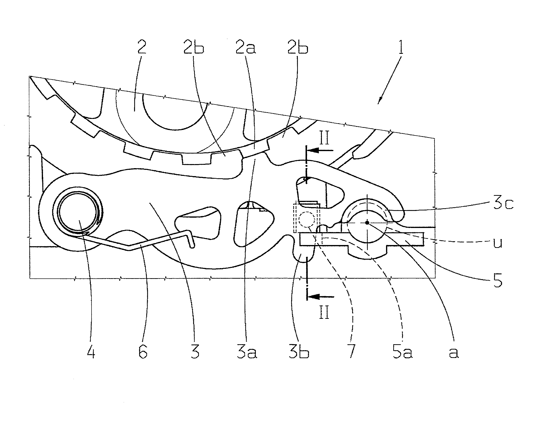
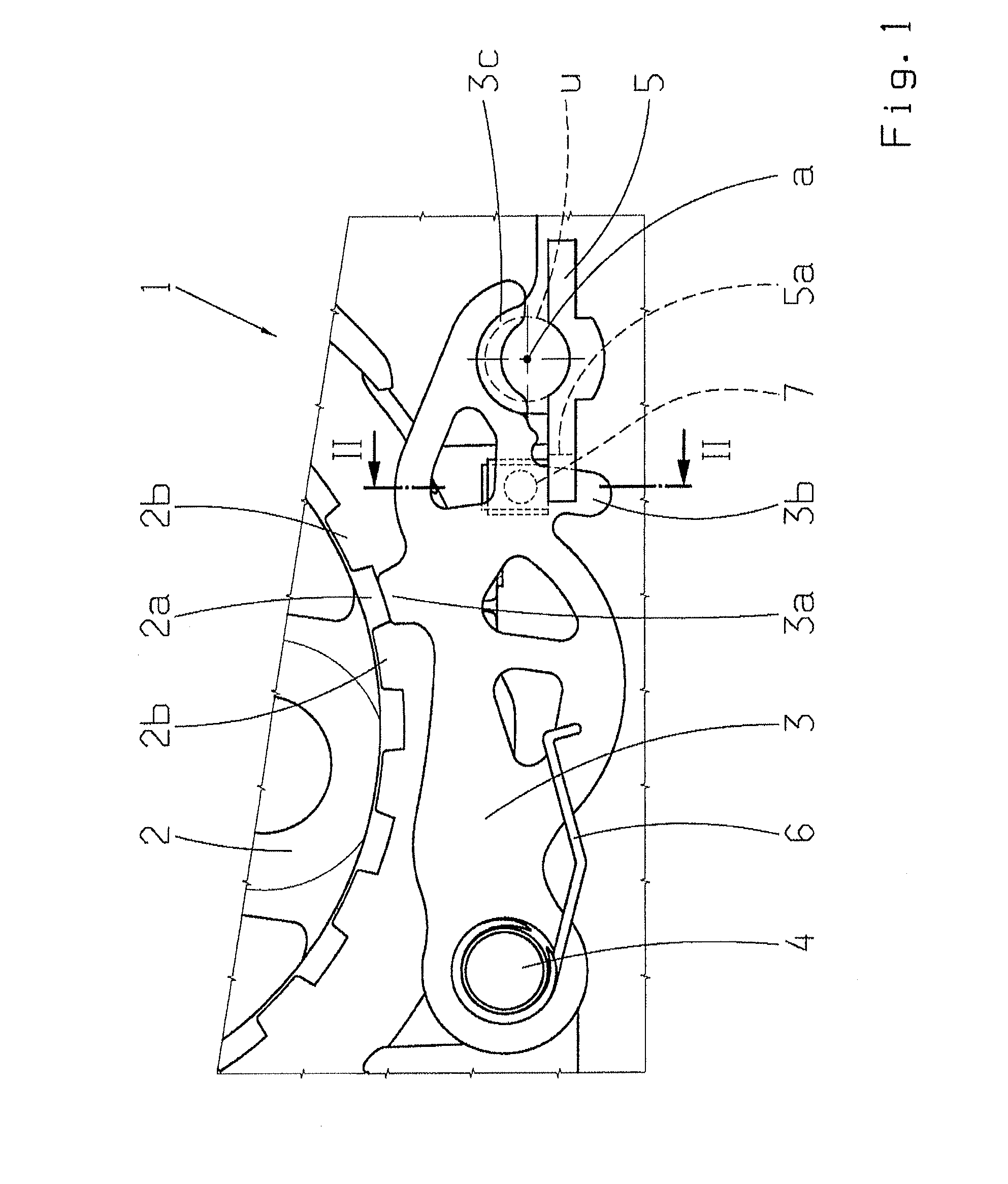
[0023]FIG. 1 shows a parking lock device 1 for an automatic transmission (not shown) of a motor vehicle, in which a parking lock gearwheel 2 (shown in part) and a locking pawl 3 mounted to pivot on a parking lock bolt 4 fixed to a housing are represented. The locking pawl 3 comprises a pawl tooth 3a, a pawl hook 3b and a curved supporting surface 3c for a locking detent, which is indicated by a dashed circular circumference-line u and an axis a. The parking lock device 1 also comprises a guide plate 5 which is supported on the housing and comprises a guide slot 5a in the area of the pawl hook 3b. The locking pawl 3 is acted upon by a lever spring 6 which functions as a restoring spring. The parking lock gearwheel 2 has a tooth array with teeth 2a and tooth gaps 2b between them. The illustration shows the locking pawl 3 and the parking lock gearwheel 2 in a so-termed tooth-on-tooth position, i.e. the tooth 3a of the locking pawl 3 is in tooth-crown contact with the tooth 2a of the pa...


PUM


Abstract

A parking lock device (1) for an automatic transmission of a motor vehicle. The parking lock device (1) comprises a locking pawl (3) that is fixed to the transmission housing and mounted so that the locking pawl (3) can pivot. The parking lock device (1) has a guiding element (3b) and a guide plate (5) fixed to and supported by the housing in which the guide element (3b) of the locking pawl (3) is guided laterally. One of a low-friction supporting element (7, 8) and an electrically insulating supporting element in a form of an insulating body (107) laterally guides the locking pawl (3).

Description

[0001]This application claims priority from German patent application serial nos. 10 2010 028 934.5 filed May 12, 2010 and 10 2010 043 260.1 filed Nov. 3, 2010.FIELD OF THE INVENTION[0002]The invention concerns a parking lock device for an automatic transmission of a motor vehicle.BACKGROUND OF THE INVENTION[0003]From DE 199 33 618 A1 by the present applicant a parking lock device for an automatic transmission is known, in which when the parking lock is engaged a locking pawl that is pivotally mounted within a transmission housing engages in a parking lock gearwheel and blocks it. In this case the locking pawl is supported by means of a locking detent, relative to a guide plate which is part of a locking mechanism. When the parking lock is engaged the locking detent exerts a transverse force on the locking pawl, which is directed parallel to the axis of the parking lock bolt (pivot axis of the locking pawl). Under the action of this transverse force, the locking pawl is held against...

Claims


Application Information

Patent Timeline
Patent Type & Authority Applications(United States)
IPC IPC(8): F16H63/36
CPCF16H63/3425
Inventor DOPFERT, HAGENLIST, MATTHIAS
Owner ZF FRIEDRICHSHAFEN AG
Why Eureka
Try Eureka