
Cyclic gravitation power generation system

a power generation system and gravitational field technology, applied in mechanical energy handling, mechanical equipment, machines/engines, etc., can solve the problems of reducing the efficiency of power generation systems, and reducing the cost of green energy

Inactive Publication Date: 2011-11-17
CHOW ALBERT
View PDF2 Cites 16 Cited by
  • Summary
  • Abstract
  • Description
  • Claims
  • Application Information

AI Technical Summary

Benefits of technology

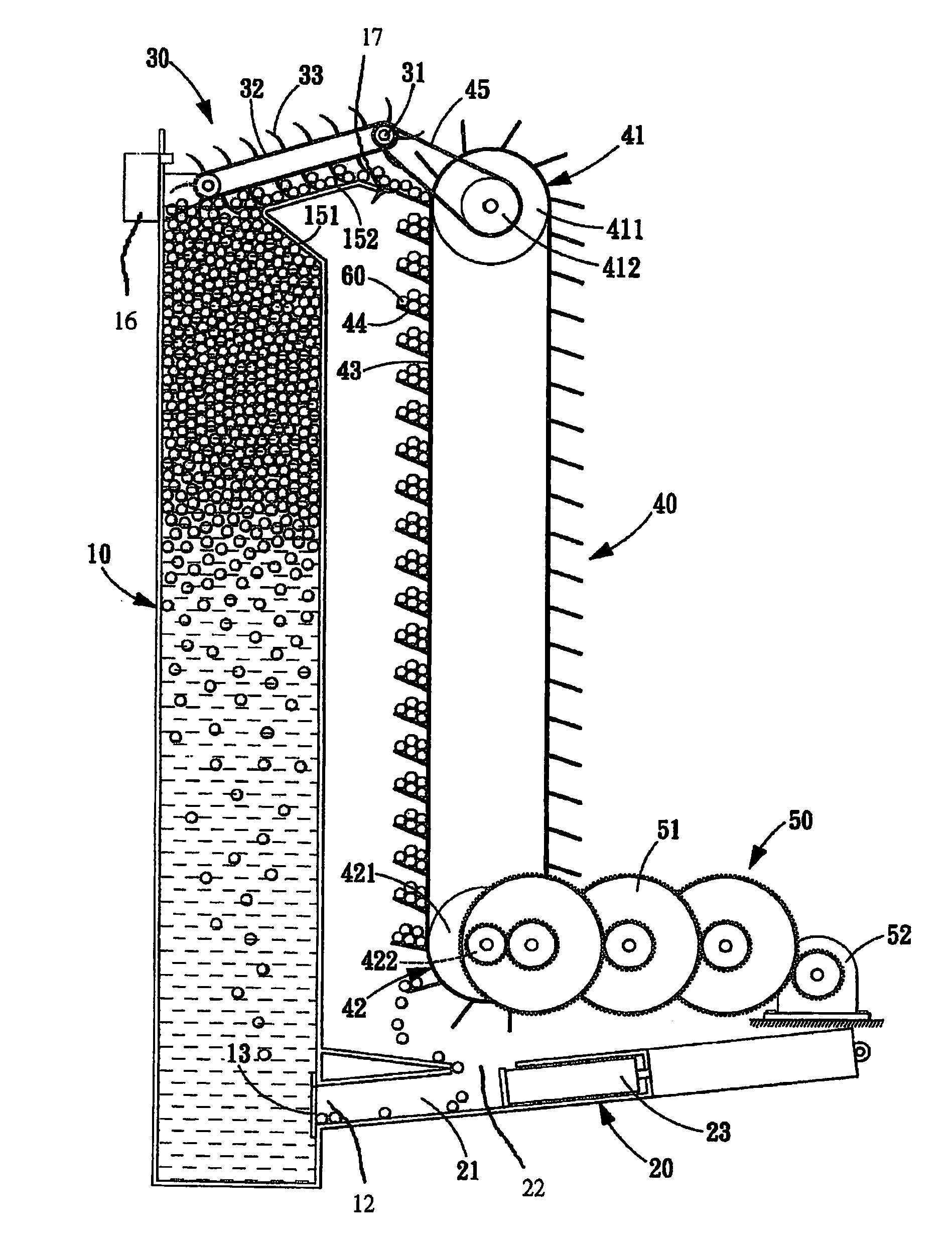
[0006]The primary objective of the present invention is to provide a cyclic gravitation power generation system, wherein potential energy is converted into kinetic energy to drive a generator to generate electric power when float balls are moved downward from a high position to a low position by gravity, and wherein a vertical water tank can make the float balls to move back to the high position from the low position to perform a cyclic operation, whereby is achieved a low-cost cyclic power generation system.

Problems solved by technology

However, the conventional power plants generate nuclear waste or emit carbon dioxide to ruin the environment.
However, the green energies are expensive and hard to harness artificially at present.
Therefore, they cannot extensively replace the conventional energy sources yet.

Method used


Image

  • Cyclic gravitation power generation system
  • Cyclic gravitation power generation system
  • Cyclic gravitation power generation system

Examples


Embodiment Construction

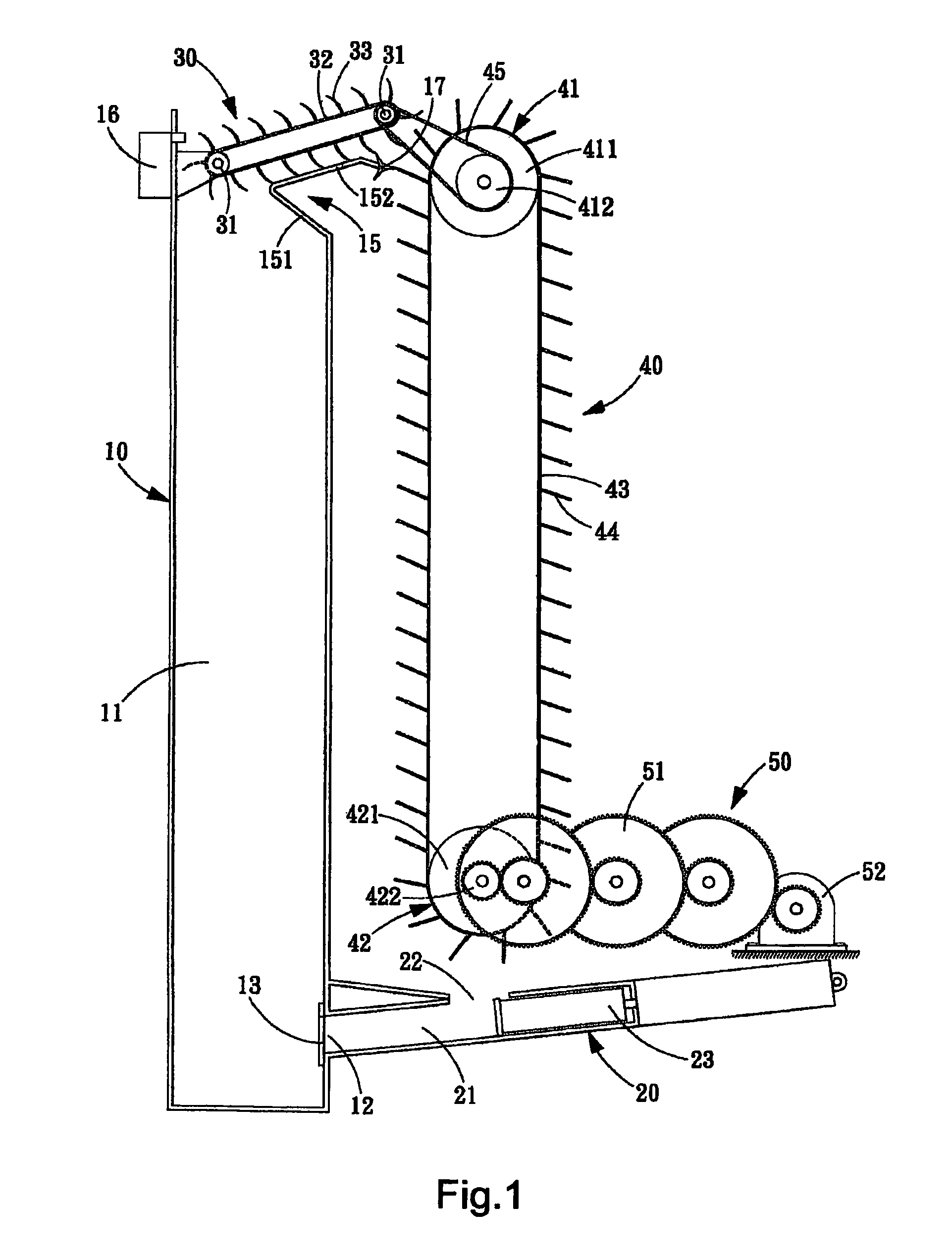
[0015]Refer to FIGS. 1-3. The cyclic gravitation power generation system of the present invention circulates float balls 60 thereinside to generate electric power and comprises a vertical water tank 10, a propulsive device 20, a guiding device 30, a carrying device 40 and a power generation device 50.

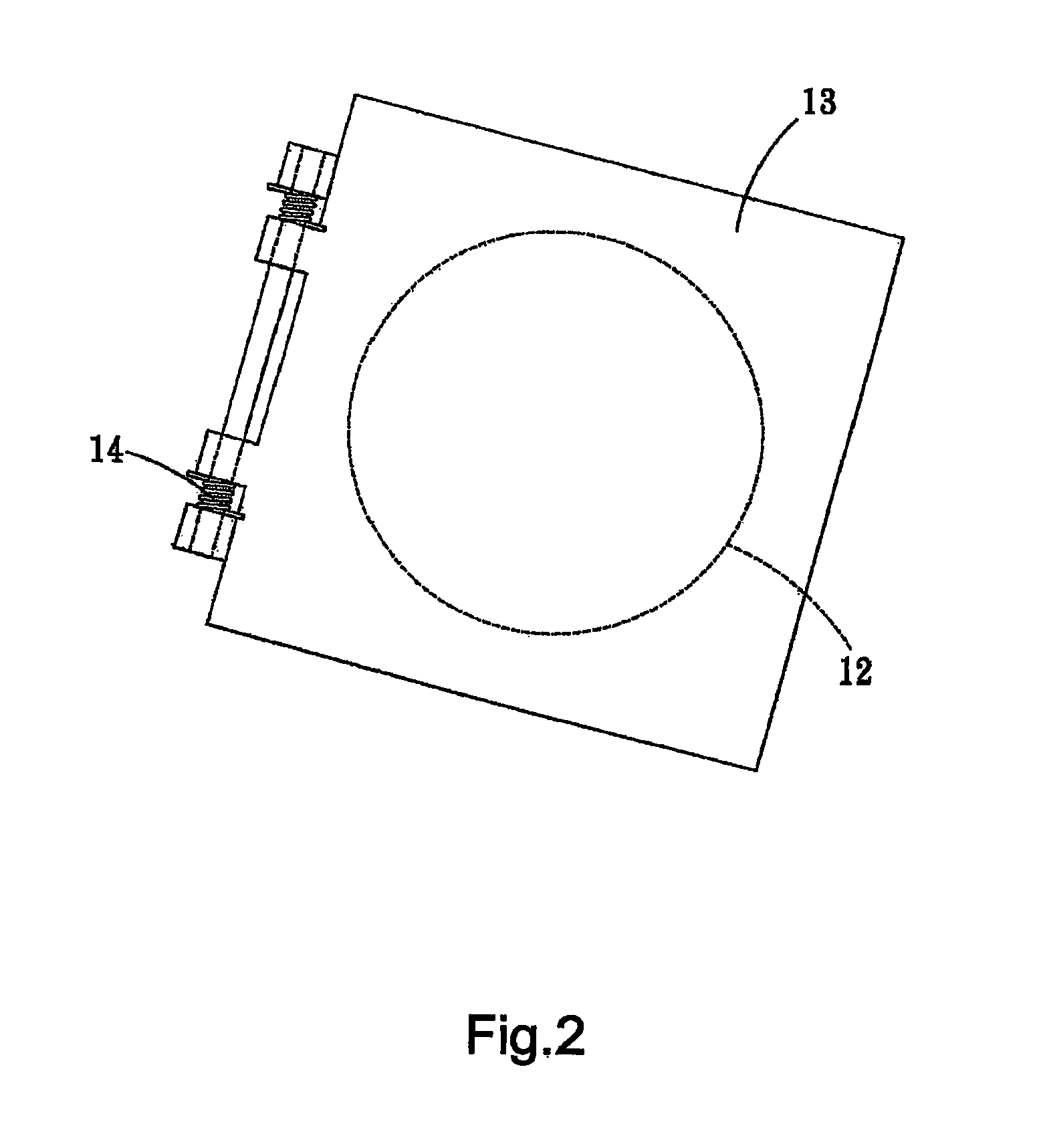
[0016]The vertical water tank 10 has a holding space 11. The holding space 11 has an aperture 12 on a side wall near the bottom thereof. A block plate 13 is hinged on the wall of the vertical water tank 10 to cover the aperture 12. A pivot of the block plate 13 has at least one torsion spring 14 to automatically restore the opened block plate 13 back to the closed state. The block plate 13 is tilted toward the bottom of the vertical water tank 10. An opening of the vertical water tank 10 has a guiding portion 15. The guiding portion 15 has a confining section 151 extending toward the interior of the vertical water tank 10 and a guiding section 152 extending outward from the vertical wat...


PUM


Abstract

The present invention proposes a cyclic gravitation power generation system, which comprises a vertical water tank, a propulsive device, a guiding device, a carrying device and a power generation device, wherein potential energy is converted into kinetic energy to drive a generator to generate electric power when float balls are moved downward from a high position to a low position by gravity, and the vertical water tank can make the float balls to be moved back to the high position to perform a cyclic operation, whereby is achieved a low-cost cyclic power generation system.

Description

FIELD OF THE INVENTION[0001]The present invention relates to a power generation system, particularly to a gravitation power generation system.BACKGROUND OF THE INVENTION[0002]In the modern world, electricity is indispensable energy for daily life as well as for industrial development.[0003]Electricity is usually generated by a nuclear power plant or a thermal power plant. However, the conventional power plants generate nuclear waste or emit carbon dioxide to ruin the environment. Therefore, much attention is paid to the green energy systems, such as the wind power generation system, hydroelectric power generation system and solar power generation system.[0004]The green energies are environment-friendly and sustainable. However, the green energies are expensive and hard to harness artificially at present. Therefore, they cannot extensively replace the conventional energy sources yet.[0005]Accordingly, the Inventor proposes a cyclic gravitation power generation system, which is expect...

Claims


Application Information

Patent Timeline
IPC IPC(8): H02K7/18F03B17/04
CPCY02E10/20F03B17/04
Inventor CHOW, ALBERT
Owner CHOW ALBERT
Learn More