Vacuum fluorescent display with driver IC

a fluorescent display and driver technology, applied in the field of vacuum fluorescent display with a driver ic, can solve the problems of display luminance drop and display quality loss, and achieve the effect of reducing display quality loss, reducing display luminance, and increasing the simplified shape of filament support itsel

Active Publication Date: 2011-11-17
NORITAKE ITRON CORP +1
View PDF5 Cites 4 Cited by
  • Summary
  • Abstract
  • Description
  • Claims
  • Application Information

AI Technical Summary

Benefits of technology

[0016]Since depressions are provided to the surface of the filament support to which one end of the filamentary cathodes is fixed, or slits are provided to the filament support, the distance between the filamentary cathodes and the phosphor can be reduced. Therefore, the vacuum fluorescent display with a driver IC according to the present invention can produce high luminance without loss of display quality, even in high-definition graphic CIG-VFDs.
[0017]Also, because one end of the filamentary cathodes is fixed to the surface of the filament support, the press-shape of the filament support itself can be more simplified compared with the conventional product. The press-shape is accordingly stable, and the die used for press becomes less expensive than the conventional product.

Problems solved by technology

It is known that the distance between a grid and an anode substrate can be reduced in order to solve this problem, but a problem has been encountered in the prior art in that reducing this distance leads to a decrease in display luminance and a loss of display quality.

Method used


Image

  • Vacuum fluorescent display with driver IC
  • Vacuum fluorescent display with driver IC
  • Vacuum fluorescent display with driver IC

Examples


Embodiment Construction

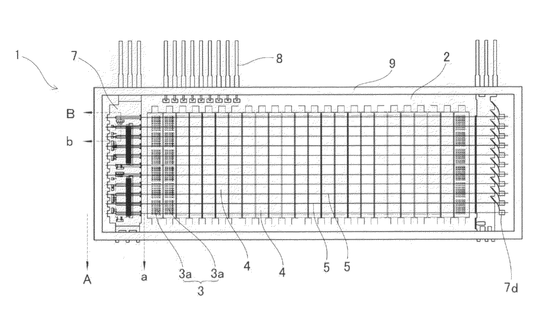
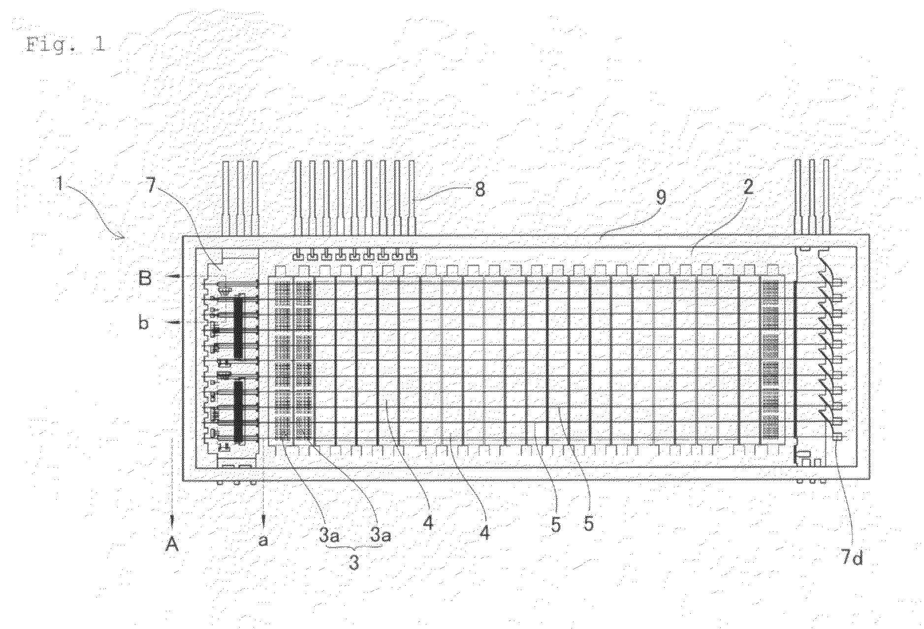
[0025]The CIG-VFD of the present invention will now be described with reference to FIGS. 1 to 3. FIG. 1 is a plan view showing the structure of the CIG-VFD, FIG. 2 is a cross-sectional view of A-a in FIG. 1, and FIG. 3 is a cross-sectional view of B-b in FIG. 1.

[0026]A CIG-VFD 1 comprises a display unit 3 comprising at least an aluminum or other wiring (not shown) on an anode substrate 2, and an anode that is formed in a matrix pattern in a predetermined area of the wires and that has a phosphor layer 3a adhered thereto, and also comprises a plurality of grids 4 provided substantially parallel to each other above the display unit 3 so as to cover the display unit 3, and a plurality of filamentary cathodes 5 installed above the grids 4, as shown in FIGS. 1 to 3. The CIG-VFD 1 also comprises a driver IC 6 mounted on the anode substrate 2 within an end cooling area 5a of the filamentary cathodes 5 and adapted to drive the display unit 3, and a filament support 7 that protectively shiel...


PUM


Abstract

The distance between filamentary cathodes and a phosphor on an anode substrate can be reduced by shortening the distance between the filamentary cathodes and a grid. To obtain high luminance without loss of display quality, the present invention provides a vacuum fluorescent display (1) with a driver IC, comprising a display unit (3) provided with a phosphor layer on an anode substrate (2), a plurality of filamentary cathodes (5), a grid (4), a driver IC (6), and a filament support (7) for shielding the IC and supporting an end part of the filamentary cathodes. The end part of the filamentary cathodes is fixed to one short side of the vacuum fluorescent display at a long side of the filament support. Depressions are provided to a surface of the filament support, or slits are provided to the filament support.

Description

TECHNICAL FIELD[0001]The present invention relates to a vacuum fluorescent display with a driver IC, and particularly relates to a filament support structure of the vacuum fluorescent display.TECHNICAL BACKGROUND[0002]Vacuum fluorescent displays with a driver IC (also referred to below as CIG-VFDs) can have a driver IC mounted inside the vacuum fluorescent display, and are therefore capable of a reduced package size, as well as high density and display capacity.[0003]A filament support provided to a metal cover of an IC shield is known in the prior art as an example of a filament support structure of a CIG-VFD (Unexamined Utility Model Application Publication No. 1-46948). Examples (Patent Reference 2, Patent Reference 3) are also known in which the filament support is provided separately from the metal IC shield to an end part of a metal frame whereon a metal IC shield for shielding the driver IC is mounted (Unexamined Utility Model Application Publication No. 5-36741, Japanese Lai...

Claims


Application Information

Patent Timeline
Patent Type & Authority Applications(United States)
IPC IPC(8): G09G3/20G06F3/038
CPCH01J31/126H01J29/96
Inventor MAEDA, TADAMI
Owner NORITAKE ITRON CORP
Why Eureka
Try Eureka