Reflex Longitudinal Imaging Using Through Sensor Insonification

a longitudinal imaging and insonification technology, applied in the field of system for gathering information, can solve the problem that not all reflected pulses are of interes

Inactive Publication Date: 2011-11-17
QUALCOMM INC
View PDF15 Cites 43 Cited by
  • Summary
  • Abstract
  • Description
  • Claims
  • Application Information

AI Technical Summary

Problems solved by technology

However, not all of the refl

Method used


Image

  • Reflex Longitudinal Imaging Using Through Sensor Insonification
  • Reflex Longitudinal Imaging Using Through Sensor Insonification
  • Reflex Longitudinal Imaging Using Through Sensor Insonification

Examples


Embodiment Construction

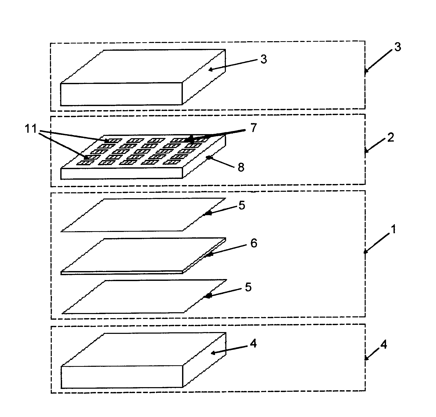
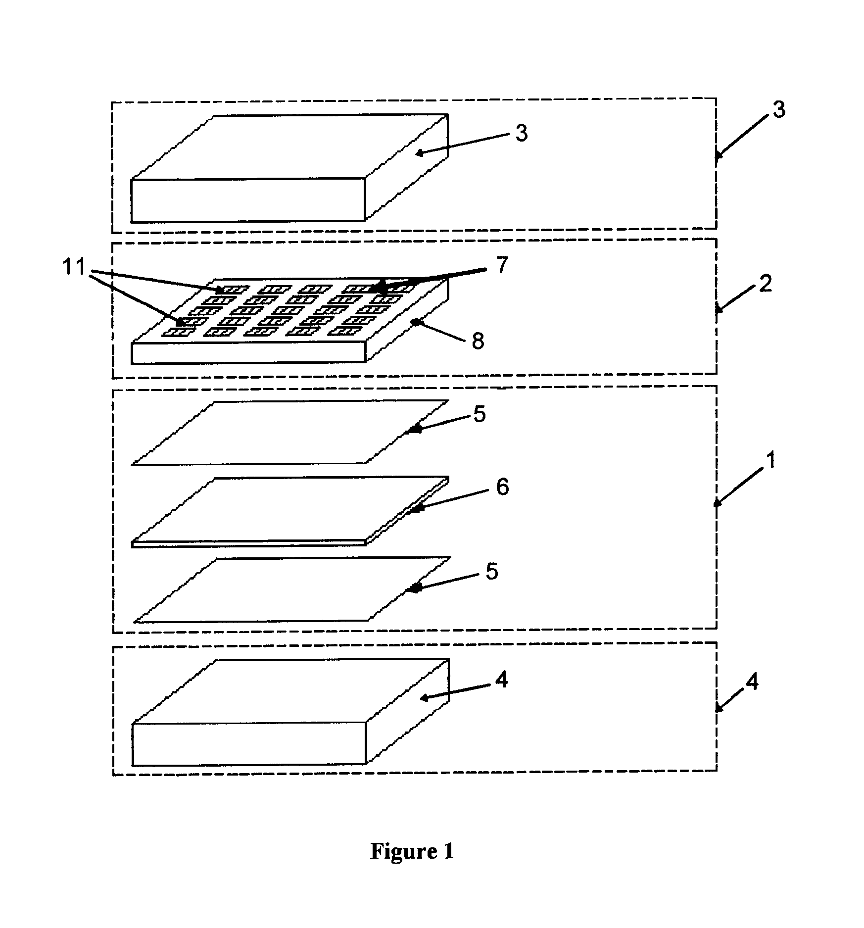
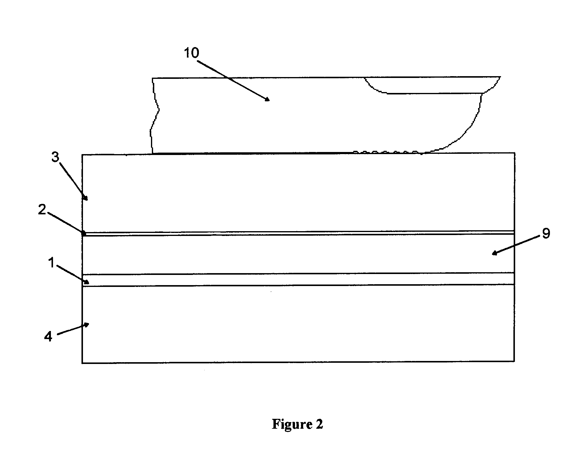
[0014]The invention described herein is illustrated by way of one or more particular embodiments. Initially, a general overview of the invention is provided, followed by additional details. The invention may be embodied as an ultrasonic reflex imaging device comprising a platen, an insonification device, and an ultrasonic receiver array positioned between the platen and the insonification device. The ultrasonic receiver array may be in physical contact with the platen. The platen may be bonded to the receiver array through an adhesive, such as an epoxy, a two-part acrylic, or a cyanoacrylate super glue. Also, the insonification device may be a plane wave generator. In another embodiment, the imaging device further comprises a backer positioned such that the insonification device is between the receiver array and the backer. The backer may be configured to absorb or delay acoustic signals.

[0015]The receiver array can be constructed from a number of suitable materials for receiving ul...


PUM


Abstract

An ultrasonic reflex imaging device and a method are described. A device according to the invention may include a platen, a generator, and a receiver positioned between the platen and the generator. A backer may be positioned so that the insonification device is between the receiver array and the backer. The backer may be configured to absorb or delay energy that originated from the generator. The generator produces an energy pulse, which travels through the receiver and the platen to reach a biological object. Part of the energy pulse is reflected from the biological object. The reflected energy pulse travels through the platen to the detector. The detector converts the reflect energy pulse to electric signals, which are then interpreted to create an image of the biological object.

Description

CROSS-REFERENCE TO RELATED APPLICATION[0001]This application claims priority to U.S. Provisional Patent Application No. 61 / 333,304, which was filed on May 11, 2010, the disclosure of which is incorporated herein by reference.FIELD OF THE INVENTION[0002]The present invention relates to a system for gathering information that can be used to create an image of an object. The information is obtained using a longitudinal wave, such as an ultrasound wave.BACKGROUND OF THE INVENTION[0003]Since the 1800's fingerprint information has been collected from human fingers and hands by means of ink and paper. For the purposes of this invention, the term fingerprint refers to the skin surface friction ridge detail of a single digit, or part of the friction ridge detail of a digit, or any portion of the skin surface friction ridge up to and including the entire hand. In recent years, various electronic fingerprint scanning systems have been developed utilizing optical, capacitance, direct pressure, ...

Claims


Application Information

Patent Timeline
IPC IPC(8): G01S15/89H04N7/18
CPCA61B5/1172G06K9/0002G01S15/8913G01S15/18G06V40/1306
Inventor SCHNEIDER, JOHN K.KITCHENS, JACK C.
Owner QUALCOMM INC
Why Eureka
Try Eureka