Alternating bipolar forming voltage for resistivity-switching elements

a resistivity-switching element and bipolar forming technology, applied in the field of nonvolatile storage, can solve problems such as time-consuming

Active Publication Date: 2011-11-17
SANDISK TECH LLC
View PDF10 Cites 23 Cited by
  • Summary
  • Abstract
  • Description
  • Claims
  • Application Information

AI Technical Summary

Problems solved by technology

One problem with the process of FORMING is that all of the non-volatile stor...

Method used


Image

  • Alternating bipolar forming voltage for resistivity-switching elements
  • Alternating bipolar forming voltage for resistivity-switching elements
  • Alternating bipolar forming voltage for resistivity-switching elements

Examples


Embodiment Construction

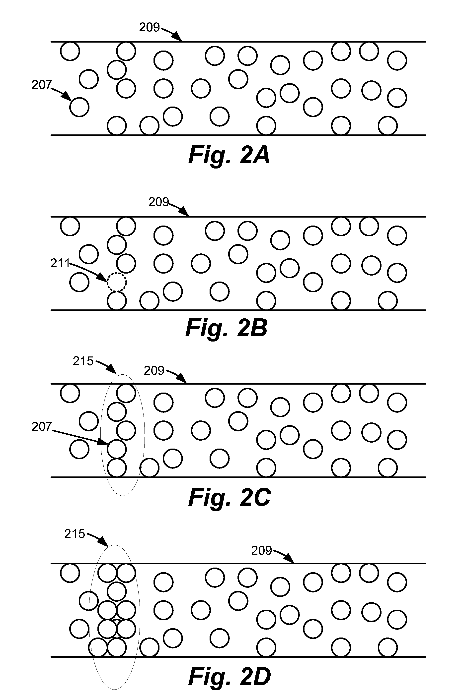
[0025]A method and system for FORMING memory cells have reversible resistivity-switching elements is described herein. FORMING refers to reducing the resistance of the reversible resistivity-switching element, and may refer to reducing the resistance for the first time. In one embodiment, the polarity of the voltage that is applied to the memory cell when forming the memory cell is alternated between application of voltages. For example, one or more voltages having one polarity are applied to the memory cell, then one or more voltages having the opposite polarity are applied. There may be a rest period between application of the voltages of opposite polarity. Forming by the use of voltages of opposite polarity may be referred to herein as “bipolar forming.”

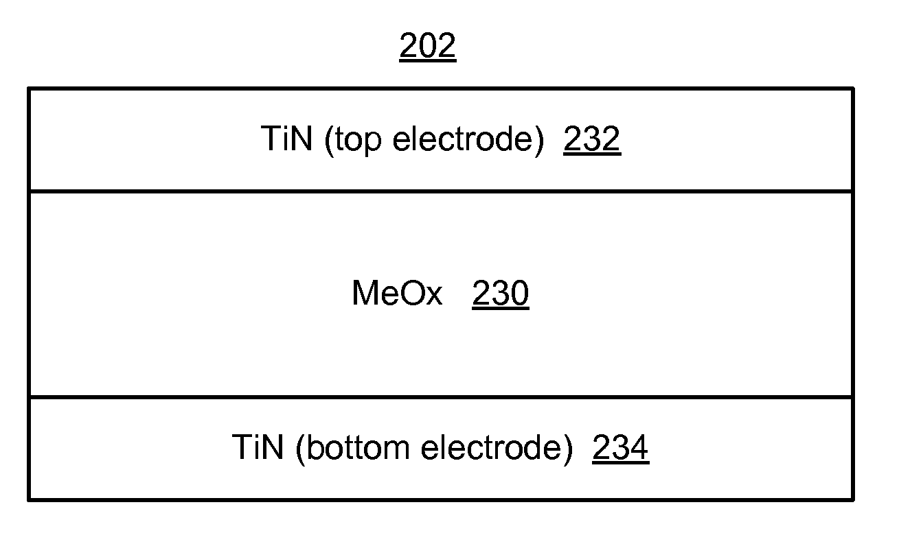
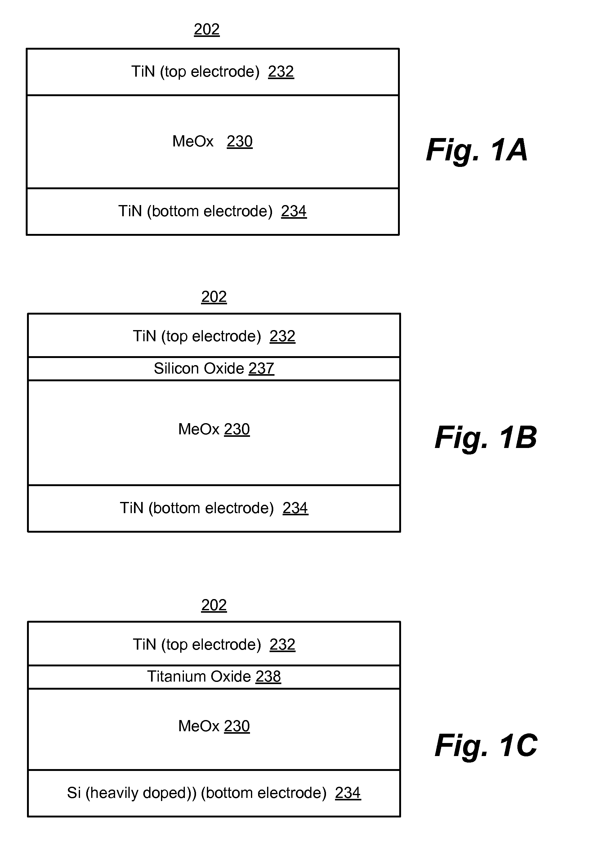
[0026]In one embodiment, the memory cell includes a metal oxide region between a top electrode and a bottom electrode. The metal oxide region may serve as the reversible resistivity-switching element. One voltage polarity may appl...


PUM


Abstract

A method and system for forming reversible resistivity-switching elements is described herein. Forming refers to reducing the resistance of the reversible resistivity-switching element, and may refer to reducing the resistance for the first time. Prior to forming the reversible resistivity-switching element it may be in a high-resistance state. The method may comprise alternating between applying one or more first voltages having a first polarity to the memory cell and applying one or more second voltages having a second polarity that is opposite the first polarity to the memory cell until the reversible resistivity-switching memory element is formed. There may be a rest period between applying the voltages of opposite polarity.

Description

PRIORITY[0001]This application claims the benefit of U.S. Provisional Application No. 61 / 333,533, entitled “Alternating Bipolar Forming Voltage for Resistivity-Switching Elements,” by Xiao et al., filed on May 11, 2010, incorporated herein by reference.BACKGROUND[0002]1. Field[0003]This application relates to technology for non-volatile storage.[0004]2. Description of the Related Art[0005]Materials having a detectable level of change in state, such as a resistance, are used to form various types of non-volatile semiconductor based memory cells. It has been proposed that such memory cells might be used for binary data storage in memory arrays by assigning a lower resistance state of a memory cells to a first logical state such as logical ‘0,’ and assigning a higher resistance state of the memory cell to a second logical state such as logical ‘1.’ Other logical data assignments to resistance states may also be used. Some materials can be reset back to a higher resistance state after b...

Claims


Application Information

Patent Timeline
IPC IPC(8): G11C11/21
CPCG11C13/0007G11C13/0069G11C2013/0073G11C2213/72G11C2013/0092G11C2213/32G11C2013/0083
Inventor XIAO, LIBANDYOPADHYAY, ABHIJITDU, TAO
Owner SANDISK TECH LLC
Why Eureka
Try Eureka