
Method and apparatus for adapting at least one set of parameters of an intelligent electronic device

a technology of intelligent electronic devices and parameters, applied in powerline communication applications, instruments, process and machine control, etc., can solve problems such as false selection, sensitivity, and sensitivity, and compromise fault selectivity and network availability in favor of reliability

Inactive Publication Date: 2011-11-17
ABB RES LTD
View PDF18 Cites 73 Cited by
  • Summary
  • Abstract
  • Description
  • Claims
  • Application Information

AI Technical Summary

Benefits of technology

"The present patent provides a method and apparatus for adapting parameters of Intelligent Electronic Devices (IEDs) in an electrical power network having multiple switching devices. The method involves reading the network status, simulating faults, and deducing new sets of parameters for the IEDs based on the network topology and status of the switching devices. The new sets of parameters are then applied to update the IEDs. The technical effect of this patent is to improve the reliability and stability of the electrical power network by optimizing the performance of the IEDs based on the network status and topology."

Problems solved by technology

However, since the protection system may respond correctly in a wide variety of different situations, often this behavior compromises fault selectivity and network availability in favor of reliability.
Further, one of the major challenges is a protection system for a microgrid which may respond to both main grid and microgrid faults, where the microgrid is connected to the main grid.
In these circumstances, problems related to selectivity (e.g., false, unnecessary tripping) and sensitivity (e.g., undetected faults or delayed tripping) of protection system may arise.
For instance, it was seen that a large difference between fault currents in main grid connected and islanded modes may create errors in the protections of microgrids.
In addition, controllable islands of different sizes and content may be formed as a result of faults in the main grid or inside a microgrid.
In such circumstances, a loss of relay coordination may happen and generic over-current (OC) protection with a single setting group may become inadequate, e.g., it will not guarantee a selective operation for all possible faults.
Otherwise, unwanted operation or failure to operate when required may occur.

Method used


Image

  • Method and apparatus for adapting at least one set of parameters of an intelligent electronic device
  • Method and apparatus for adapting at least one set of parameters of an intelligent electronic device
  • Method and apparatus for adapting at least one set of parameters of an intelligent electronic device

Examples


first practical example

[0151]In FIG. 3, an embodiment shows an example from the feeder automation. FIG. 3 shows two feeders 10, 20 with a normally open switch (tie switch) CB1 in between. An over-current protection is installed at a level of each circuit breaker CB1, CB11, CB12, CB13, CB14, CB21, CB22, CB23 and CB24.

[0152]The first feeder 10 and the second feeder 20 are powered by different sources 12, 22 and separated by a normally open switch (or tie switch) CB1. Further, FIG. 3 shows multiple loads L11, L12, L13, L14, L21, L22, L23 and L24. Protection of the network is ensured by over-current protection functions running in IEDs at the level of each circuit breaker CB11, CB12, CB13, CB14, CB21, CB22, CB23 and CB24. In the present example, switches are circuit breakers in order to simplify the discussion.

[0153]As it is shown in FIG. 4, a fault may occur on the line towards the load L12. If properly engineered (e.g., if the protection parameters of all over-current protection functions are properly set),...

second practical example

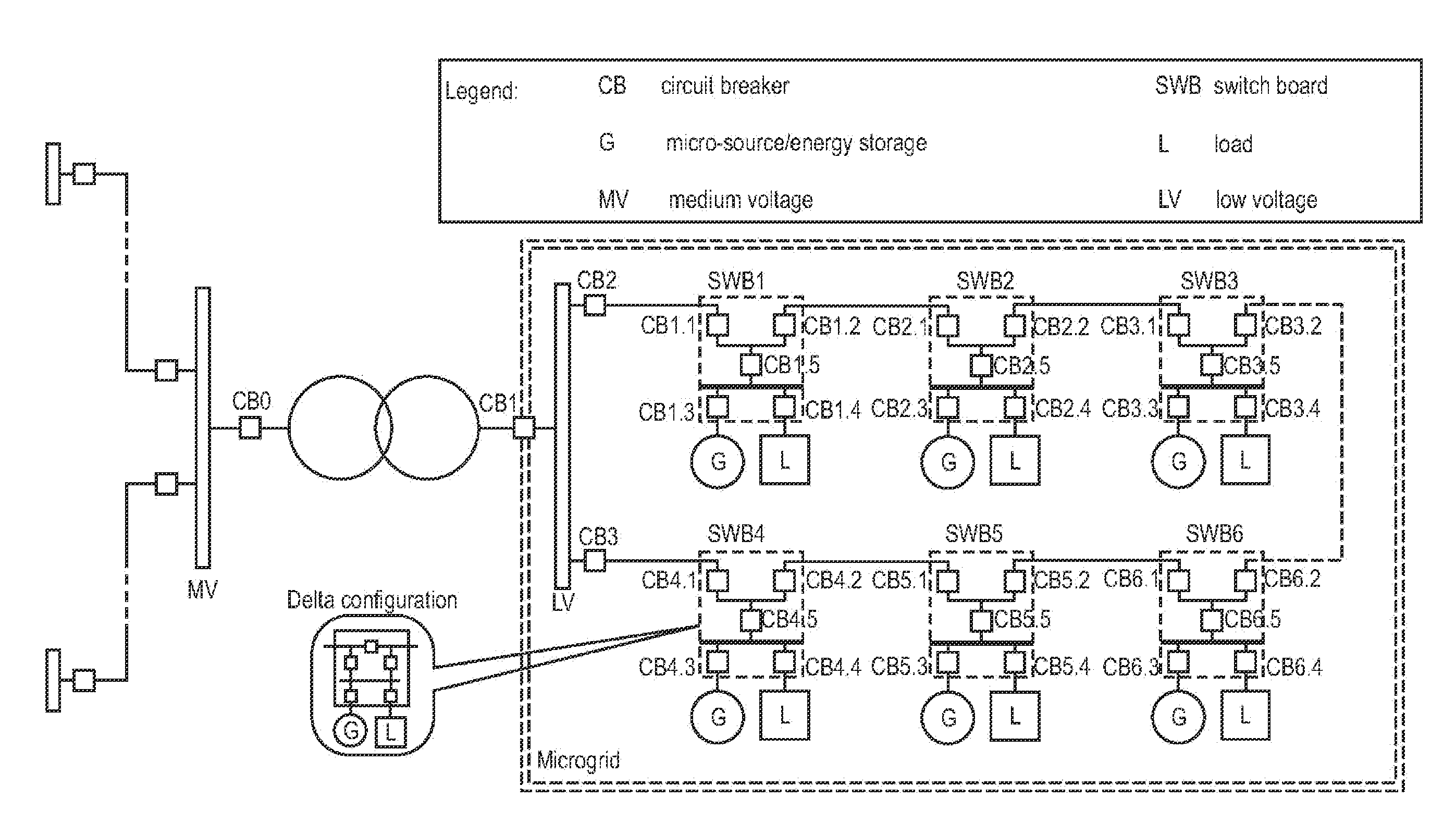
[0163]In the following, embodiments with distributed energy resources are described. As compared to the network shown in FIGS. 3 to 5, the distribution network shown FIG. 6 includes at each feeder several distributed energy resources (DER) units that are marked with G. The DER may be, for example, a micro-source or an energy storage source. The microgrid is connected to the main medium voltage (MV) grid when the circuit breaker (CB) CB1 is closed. The circuit breakers CB2 and CB3 are normally closed and circuit breakers CB 3.2 and 6.2 are normally opened. Therefore, the network shown in FIG. 6 includes a low voltage (LV) part with a first feeder with circuit breaker CB2 and switch boards SWB1, SWB2 and SWB2 and a second feeder with circuit breaker CB3 and switch boards SWB3, SWB5 and SWB6.

[0164]A protection of distribution grid where feeders are radial with loads tapped-off along feeder sections can be designed assuming a unidirectional power flow and is based on OC relays with time...


PUM


Abstract

The disclosure concerns a method and an apparatus for adapting at least one set of parameters to at least one Intelligent Electronic Device (IED) of an electrical power network having a plurality of switching devices (CB). The method includes: a) reading the current network status of the electrical power network, wherein the network status includes the status of the plurality of switching devices; b) simulating at least one network fault in the electrical power network; c) deducing at least one new set of parameters for the at least one IED using a simulated fault current induced by the at least one simulated network fault under consideration of the present network status and the network topology of the electrical power network; and d) setting the at least one set of parameters in at least one of the at least one IED. The apparatus a) reads the current network status of the electrical power network, b) selects the at least one set of parameters for the at least one Intelligent Electronic Device out of a plurality of sets of parameters depending of the current network status; and c) sets the at least one set of parameters in the at least one IED.

Description

RELATED APPLICATION[0001]This application claims priority as a continuation under 35 U.S.C. §120 to PCT / EP2009 / 066384 filed on Dec. 3, 2009 designating the U.S., and under 35 U.S.C. §119 to EP 08170550.1 filed on Dec. 12, 2008, the entire contents of which are hereby incorporated by reference in their entireties.FIELD[0002]The present disclosure relates to a method for applying at least one set of parameters to at least one Intelligent Electronic Device (IED) of an electrical power network having a plurality of switching devices. The present disclosure also relates to an apparatus configured to apply at least one set of parameters to at least one IED of an electrical power network having a plurality of switching devices.BACKGROUND INFORMATION[0003]A power network is protected from failures (e.g., short-circuits) through the use of Intelligent Electronic Devices (IEDs). The protection functions in an IED have been standardized, for example, in an IEEE / ANSI standard and are available ...

Claims


Application Information

Patent Timeline
Patent Type & Authority Applications(United States)
IPC IPC(8): G06F1/28
CPCH04B3/54H02H3/006H04B2203/5458H04B2203/5495
Inventor OUDALOV, ALEXANDREGOERLITZ, OTMARKOCH, THOMASZHANG, YANFREI, CHRISTIAN
Owner ABB RES LTD
Learn More