Encoding method, decoding method, coder and decoder

a technology of encoder and decoder, applied in the direction of coding, code conversion, error correction/detection using convolutional codes, etc., can solve the problems of avoiding the change of coding rate or the transmission of redundant sequences through padding or puncturing, and achieve high error correction capability and secure high data quality

Active Publication Date: 2011-11-17
PANASONIC INTELLECTUAL PROPERTY CORP OF AMERICA
View PDF2 Cites 28 Cited by
  • Summary
  • Abstract
  • Description
  • Claims
  • Application Information

AI Technical Summary

Benefits of technology

[0055]The present invention can achieve high error correc

Problems solved by technology

A problem with applying an LDPC code, which is a block code, to a system of this kind is, for example, how to make a fixed-length LDPC code block correspond to a variable-length Eth

Method used


Image

  • Encoding method, decoding method, coder and decoder
  • Encoding method, decoding method, coder and decoder
  • Encoding method, decoding method, coder and decoder

Examples


embodiment 1

[0666]The present embodiment will describe a code configuration method of an LDPC-CC based on a parity check polynomial of a time varying period greater than 3 having excellent error correction capability.

[0667][Time Varying Period of 6]

[0668]First, an LDPC-CC of a time varying period of 6 will be described as an example.

[0669]Consider Equations 27-0 to 27-5 as parity check polynomials (that satisfy 0) of an LDPC-CC of a coding rate of (n−1) / n (n is an integer equal to or greater than 2) and a time varying period of 6.

[27]

(Da#0,1,1+Da#0,1,2+Da#0,1,3)X1(D)+(Da#0,2,1+Da#0,2,2+Da#0,2,3)X2(D)+ . . . +(Da#0,n−1,1+Da#0,n−1,2+Da#0,n−1,3)Xn−1(D)+(Db#0,1+Db#0,2+Db#0,3)P(D)=0  (Equation 27-0)

(Da#1,1,1+Da#1,1,2+Da#1,1,3)X1(D)+(Da#1,2,1+Da#1,2,2+Da#1,2,3)X2(D)+ . . . +(Da#1,n−1,1+Da#1,n−1,2+Da#1,n−1,3)Xn−1(D)+(Db#1,1+Db#1,2+Db#1,3)P(D)=0  (Equation 27-1)

(Da#2,1,1+Da#2,1,2+Da#2,1,3)X1(D)+(Da#2,2,1+Da#2,2,2+Da#2,2,3)X2(D)+ . . . +(Da#2,n−1,1+Da#2,n−1,2+Da#2,n−1,3)Xn−1(D)+(Db#2,1+Db#2,2+Db#2,3)P(D...

embodiment 2

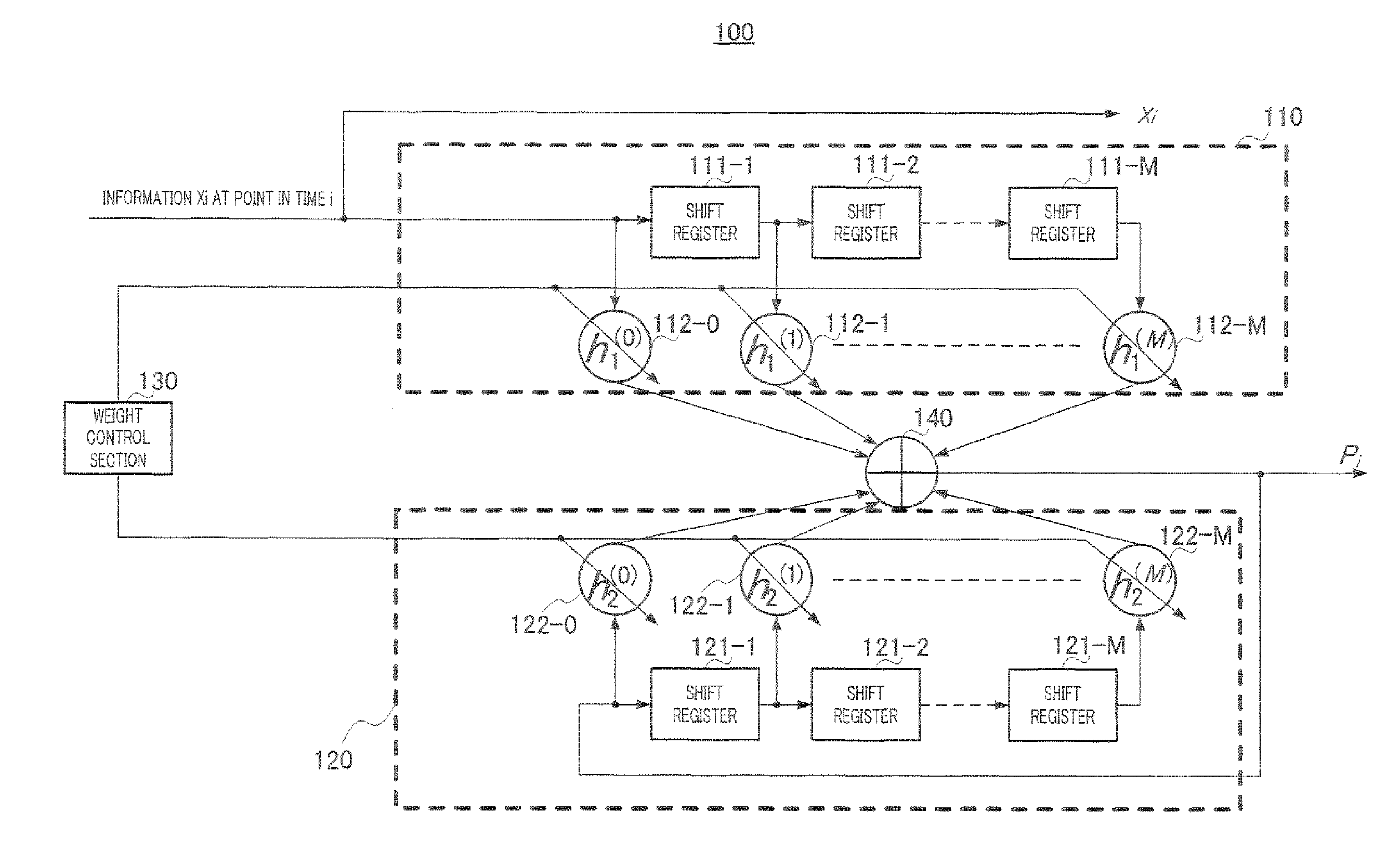
[0931]The present embodiment will describe, in detail, an LDPC-CC encoding method and the configuration of an encoder based on the parity check polynomials described in Embodiment 1.

[0932]First, consider an LDPC-CC of a coding rate of 1 / 2 and a time varying period of 3 as an example. Parity check polynomials of a time varying period of 3 are provided below.

[42]

(D2+D1+1)X1(D)++(D3+D1+1)P(D)=0  (Equation 42-0)

(D3+D1+1)X1(D)+(D2+D1+1)P(D)=0  (Equation 42-1)

(D3+D2+1)X1(D)+(D3+D2+1)P(D)=0  (Equation 42-2)

[0933]At this time, P(D) is obtained as shown in the equations below.

[43]

P(D)=(D2+D1+1)X1(D)+(D3+D1)P(D)  (Equation 43-0)

P(D)=(D3+D1+1)X1(D)+(D2+D1)P(D)  (Equation 43-1)

P(D)=(D3+D2+1)X1(D)+(D3+D2)P(D)  (Equation 43-2)

[0934]Equations 43-0 to 43-2 are then represented as follows:

[44]

P[i]=X1[i]⊕X1[i−1]⊕X1[i−2]⊕P[i−1]⊕P[i−3]  (Equation 44-0)

P[i]=X1[i]⊕X1[i−1]⊕X1[i−3]⊕P[i−1]⊕P[i−2]  (Equation 44-1)

P[i]=X1[i]⊕X1[i−2]⊕X1[i−3]⊕P[i−2]⊕P[i−3]  (Equation 44-2)

[0935]where the symbol “⊕” represents t...

embodiment 3

[0953]The present embodiment will specifically describe a code configuration method for achieving higher error correction capability when simple tail-biting described in Non-Patent Literatures 10 and 11 is performed for an LDPC-CC based on the parity check polynomials described in Embodiment 1.

[0954]A case has been described in Embodiment 1 where a g-th (g=0, 1, . . . , q−1) parity check polynomial of an LDPC-CC of a time varying period of q (q is a prime number greater than 3) and a coding rate of (n−1) / n is represented as shown in equation 36. The number of terms of each of X1(D), X2(D), . . . , Xn−1(D) and P(D) in equation 36 is 3 and in this case, Embodiment 1 has specifically described the code configuration method (constraint condition) for achieving high error correction capability. Moreover, Embodiment 1 has pointed out that even when the number of terms of one of X1(D), X2(D), . . . , Xn−1(D) and P(D) is 1 or 2, high error correction capability may be likely to be achieved....


PUM


Abstract

An encoding method and encoder of a time-varying LDPC-CC with high error correction performance are provided. In an encoding method of performing low density parity check convolutional coding (LDPC-CC) of a time varying period of q using a parity check polynomial of a coding rate of (n−1)/n (where n is an integer equal to or greater than 2), the time varying period of q is a prime number greater than 3, the method receiving an information sequence as input and encoding the information sequence using equation 1 as a g-th (g=0, 1, . . . q−1) parity check polynomial to satisfy 0:
(Da#g,1,1+Da#g,1,2+Da#g,1,3)X1(D)+(Da#g,2,1+Da#g,2,1+Da#g,2,2+Da#g,2,3)X2(D)+ . . . +(Da#g,n−1,1+Da#g,n−1,2+Da#g,n−1,3)Xn−1(D)+(Db#g,1+Db#g,2+1)P(D)=0  (Equation 1)
    • where, in equation 1:
    • “%” represents a modulo and each coefficient satisfies the following with respect to k=1, 2, . . . , n−1:
    • a#0,k,1%q=a#1,k,1%q=a#2,k,1%q=a#3,k,1%q= . . . =a#g,k,1%q= . . . =a#q−2,k,1%q=a#q−1,k,1%q=vp=k (vp=k: fixed value);
    • b#0,1%q=b#1,1%q=b#2,1%q=b#3,1%q= . . . =b#g,1%q= . . . =b#q−2,1%q=b#q−1,1%q=w (w: fixed value);
    • a#0,k,2%q=a#1,k,2%q=a#2,k,2%q=a#3,k,2%q= . . . =a#g,k,2%q= . . . =a#q−2,k,2%q=a#q−1,k,2%q=yp=k (yp=k: fixed value);
    • b#0,2%q=b#1,2%q=b#2,2%q=b#3,2%q= . . . =b#g,2%q= . . . =b#q−2,2%q=b#q−1,2%q=z (z: fixed value); and
    • a#0,k,3%q=a#1,k,3%q=a#2,k,3%q=a#3,k,3%q= . . . =a#g,k,3%q= . . . =a#q−2,k,3%q=a#q−1,k,3%q=sp=k (sp=k: fixed value);
    • a#g,k,1, a#g,k,2 and a#g,k,3 are natural numbers equal to or greater than 1 and a#g,k,1≠a#g,k,2, a#g,k,1≠a#g,k,3 and a#g,k,2≠a#g,k,3 hold true;
    • b#g,1 and b#g,2 are natural numbers equal to or greater than 1 and b#g,1≠b#g,2 holds true; and
    • vp=k and yp=k are natural numbers equal to or greater than 1.

Description

TECHNICAL FIELD[0001]The present invention relates to an encoding method, decoding method, encoder and decoder using low density parity check convolutional codes (LDPC-CC) supporting a plurality of coding rates.BACKGROUND ART[0002]In recent years, attention has been attracted to a low-density parity-check (LDPC) code as an error correction code that provides high error correction capability with a feasible circuit scale. Because of its high error correction capability and ease of implementation, an LDPC code has been adopted in an error correction coding scheme for IEEE802.11n high-speed wireless LAN systems, digital broadcasting systems, and so forth.[0003]An LDPC code is an error correction code defined by low-density parity check matrix H. Furthermore, the LDPC code is a block code having the same block length as the number of columns N of check matrix H (see Non-Patent Literature 1, Non-Patent Literature 2, Non-Patent Literature 3). For example, random LDPC code, QC-LDPC code (Q...

Claims


Application Information

Patent Timeline
IPC IPC(8): H03M13/07G06F11/10
CPCH03M13/1111H03M13/1154H03M13/1105H03M13/13H03M13/157H03M13/23H04L1/0041H04L1/0057
Inventor MURAKAMI, YUTAKA
Owner PANASONIC INTELLECTUAL PROPERTY CORP OF AMERICA
Why Eureka
Try Eureka