Garden shears

a shear and garden technology, applied in the field of garden shears, can solve the problems of increasing cutting strength, increasing costs, and cutting stress to concentrate at the pivot connection, so as to reduce cutting-induced exhaustion, improve cutting efficiency, and increase structural strength

Active Publication Date: 2011-11-24
JIIN HAUR INDAL
View PDF20 Cites 22 Cited by
  • Summary
  • Abstract
  • Description
  • Claims
  • Application Information

AI Technical Summary

Benefits of technology

[0008]With the above-mentioned structure, the following benefits can be obtained: 1. because the pressing handle member has the pressing handle elements sandwiching the separator and the blade member pivoted onto one end of the separator, and the gripping member uses the handle elements sandwiching the assembly member, the pivot connection between the pressing handle member and the handle member provides a cutting structure with greater structural strength. 2. The pressing handle member and the gripping member 30 rotate around the first pivot apertures and the pressing handle member and the blade member rotate around the shaft apertures such that the cutting stress is not concentrated at a single pivot connection, which can improve the cutting efficiency and reduce the cutting-induced exhaustion.

Problems solved by technology

However, when using typical cutting shears for the trimming of plants, it is common to add an anvil at one end of the blade to improve the cutting efficiency of the garden shears, which can not only increase cutting strength but also provides a stronger gripping strength.
However, in order to ensure strong structural strength, the blade and the handle both need to be heavy, which causes inconvenience and leads to higher costs.
Further, the shears only have one pivot connection which causes cutting stresses to concentrate at the pivot connection.

Method used


Image

  • Garden shears
  • Garden shears
  • Garden shears

Examples


Embodiment Construction

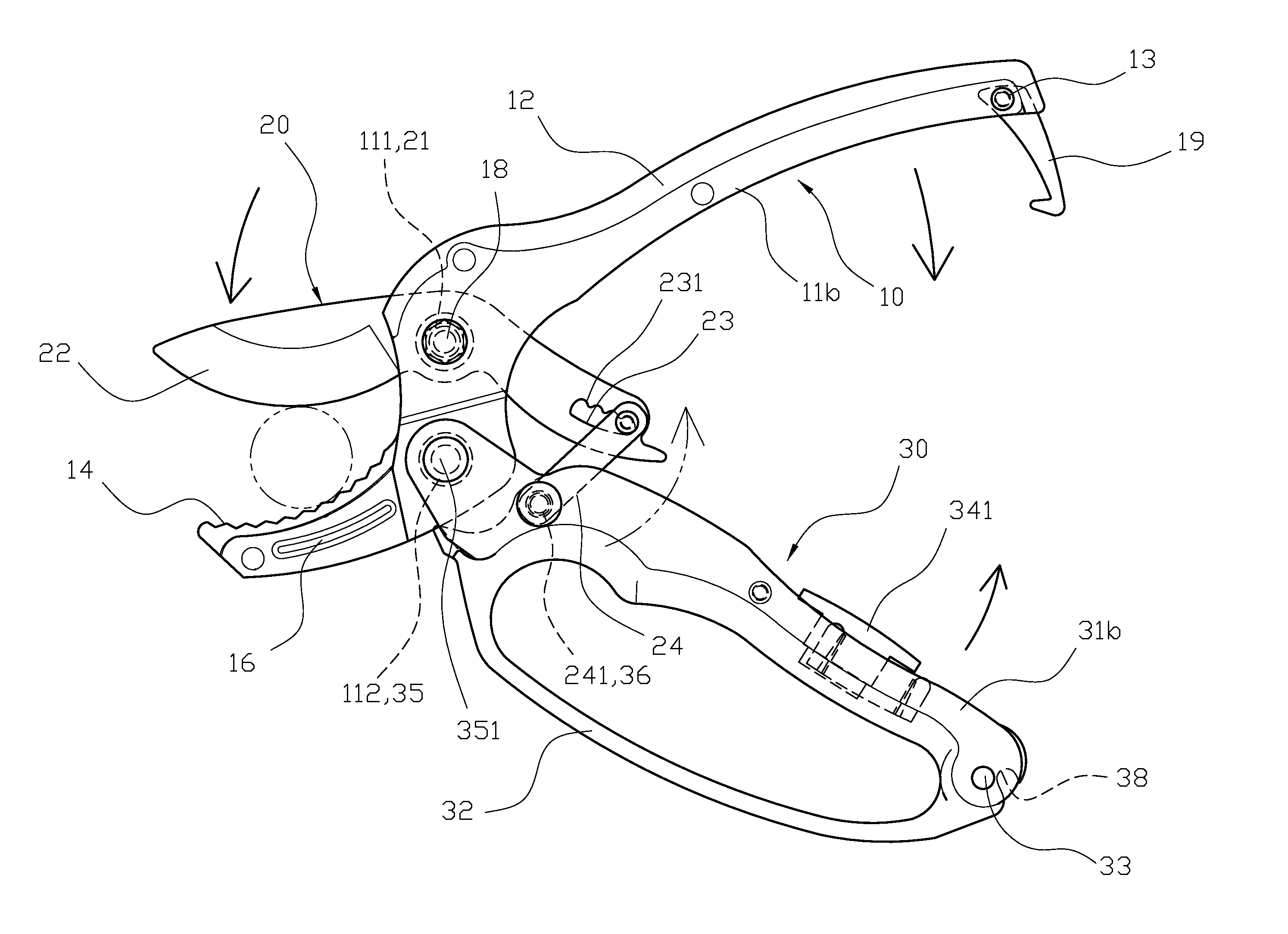
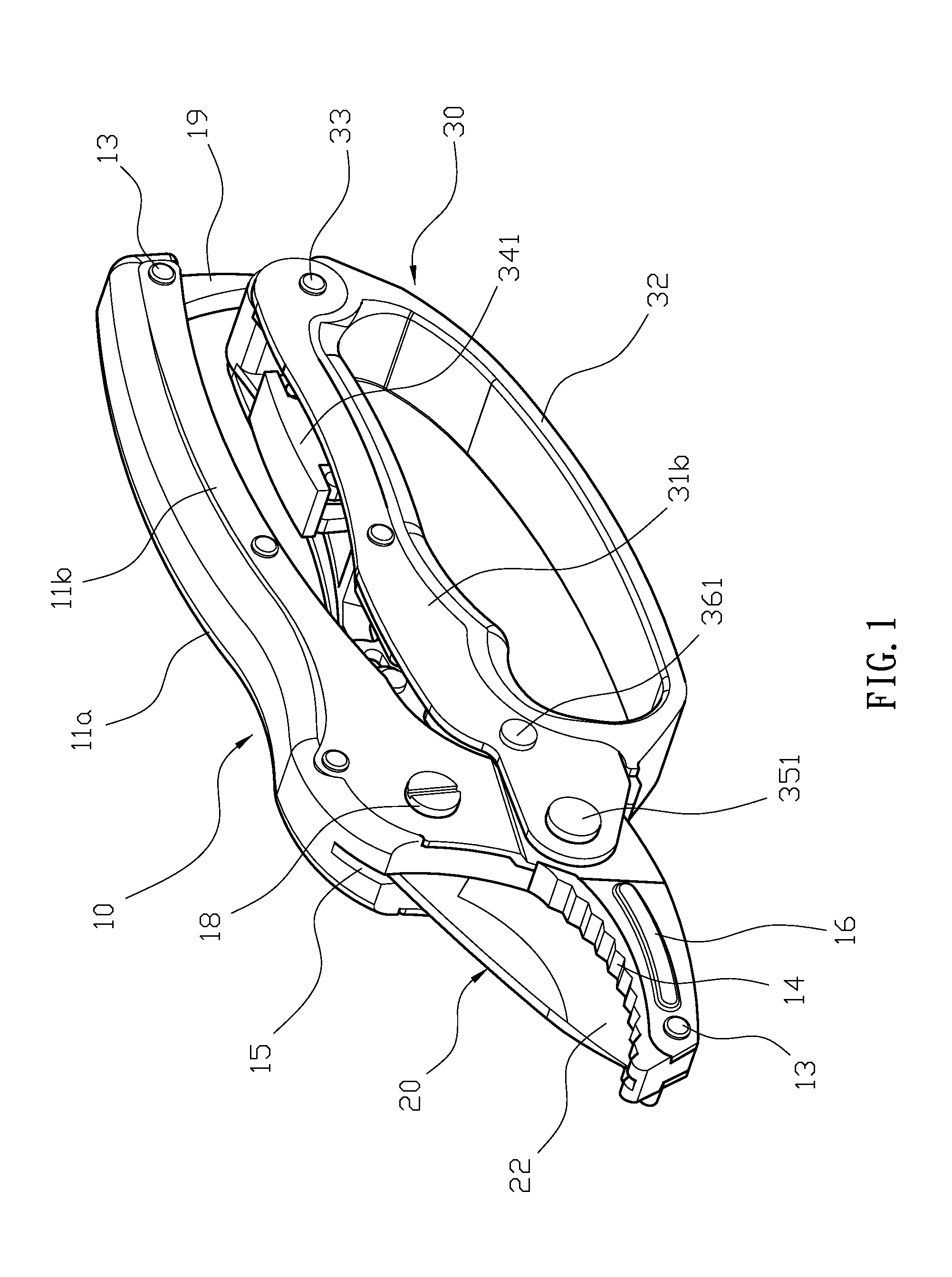
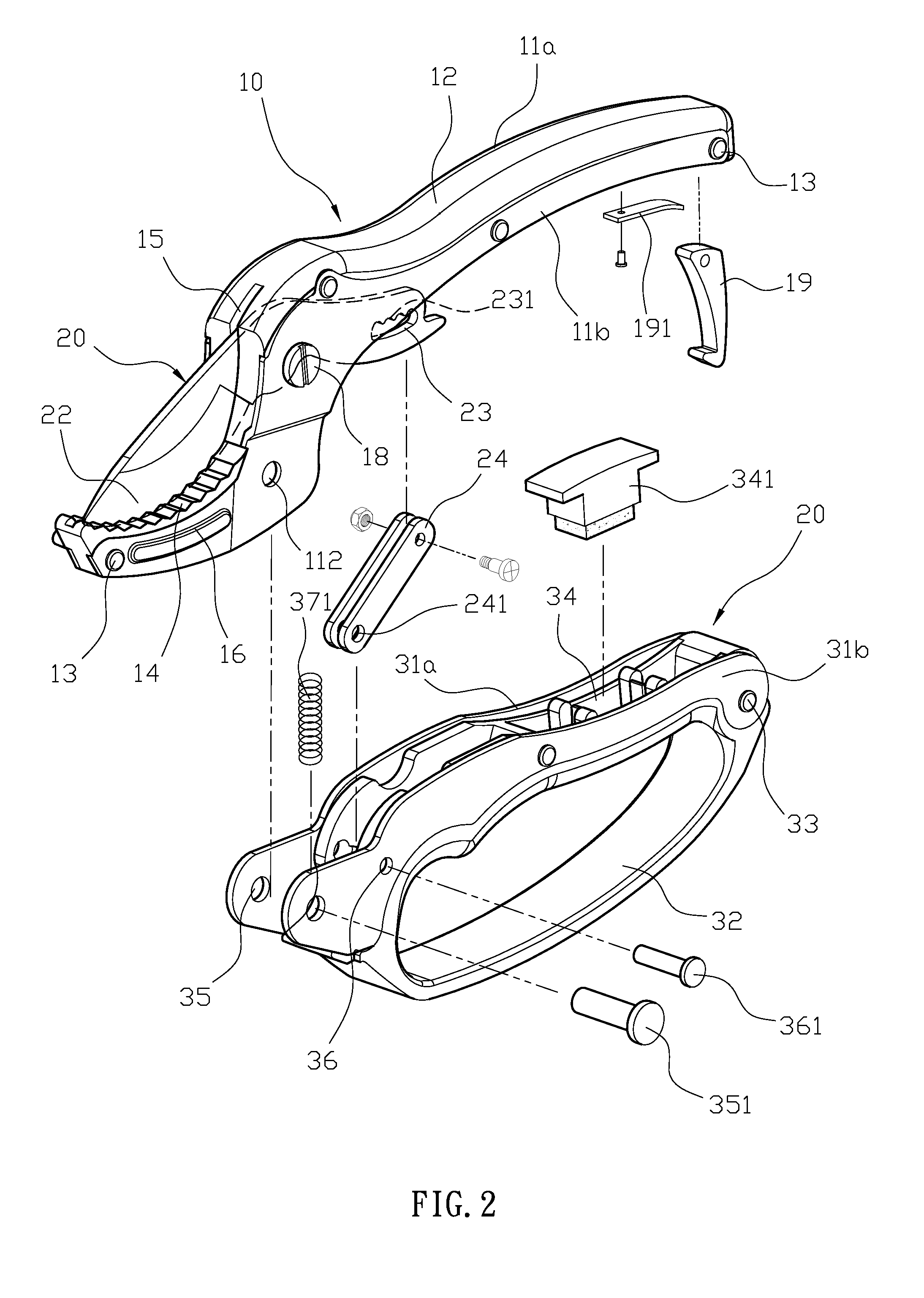
[0017]Please refer to FIG. 1, FIG. 2 and FIG. 3. A garden shears structure comprises a pressing handle member 10, a blade member 20 and a gripping member 30. The pressing handle member 10 has two symmetric pressing handle elements 11a, 11b sandwiching a separator 12. The pressing handle elements 11a, 11b and the separator 12 all have a plurality of assembly apertures A, and a plurality of the securing pins 13 that respectively pass through the assembly apertures A to sandwich the separator 12 between the two pressing handle elements 11a, 11b. The separator 12 is made of plastic or elastic materials, such as rubber. The separator 12 and the pressing handle elements 11a, 11b each respectively have a shaft aperture 111, 121 and a first pivot aperture 112, 122 at a middle section. The separator 12 has an anvil 14 formed on one side of the first pivot aperture 122. The anvil 14 has a toothed arced surface, and a cutting slot 141 is formed along a centerline of the arced surface. A first ...


PUM


Abstract

A pressing handle member of garden shears has two symmetric pressing handle elements sandwiching a separator. The separator and the pressing handle elements each respectively have a shaft aperture and a first pivot aperture. The separator has an anvil. A blade member is inserted in a first slot of the separator and pivoted onto a bolt that is disposed through the shaft aperture. Two connecting members are slidably coupled to an adjusting slot in the blade member. The gripping member has two symmetric handle elements sandwiching an assembly member. Each handle element has a second pivot aperture; a pin is placed through the second pivot apertures and the first pivot apertures of the pressing handle member. The gripping member also has a second through aperture and a joint is placed through the second through aperture and the connecting apertures of the connecting members.

Description

BACKGROUND OF THE INVENTION[0001]1. Field of the Invention[0002]The present invention relates to garden shears, and more particularly to garden shears that are capable of preventing cutting stress focusing on a single pivot to improve cutting efficiency and reduce cutting-induced exhaustion.[0003]2. Description of the Related Art[0004]Currently, the typical cutting shears structure has two members pivoted together which respectively have two handles at one end and two symmetric blades facing each other placed at the opposite ends. When the handles are pressed together, the blades are capable of shearing an object between the blades. However, when using typical cutting shears for the trimming of plants, it is common to add an anvil at one end of the blade to improve the cutting efficiency of the garden shears, which can not only increase cutting strength but also provides a stronger gripping strength. However, in order to ensure strong structural strength, the blade and the handle bo...

Claims


Application Information

Patent Timeline
Patent Type & Authority Applications(United States)
IPC IPC(8): A01G3/02
CPCA01G3/02A01G3/021B26B13/22B26B13/26B26B17/00B26B17/02
Inventor WU, SHIH-PIAO
Owner JIIN HAUR INDAL
Why Eureka
Try Eureka