Telescopable strut for turkey decoy

Inactive Publication Date: 2011-11-24
SLOOP STEPHEN S
View PDF83 Cites 4 Cited by
  • Summary
  • Abstract
  • Description
  • Claims
  • Application Information

AI Technical Summary

Benefits of technology

[0019]Such an assembly comprises two essentially inflexible, upper (outer) and lower (inner) struts, the upper strut necessarily being tubular, and the lower being either tubular or solid, such that at least 50% of the inner strut is telescopable within the outer strut. Upon being secured in the decoy, neither strut in the assembly is detachable relative to the other because the upper strut is removably securely fixed in an aperture in the upper surface of the decoy's body at any chosen time prior to deploying the decoy

Problems solved by technology

In poor lighting conditions, it is easy to find the lower aperture in the lower body and to thrust the upper tube of the assembly through the lower body aperture, but it is difficult to see the first and second apertures in the upper surface of the body of the decoy, so it is difficult to thrust the tapered upper end of the upper strut of t

Method used


Image

  • Telescopable strut for turkey decoy
  • Telescopable strut for turkey decoy
  • Telescopable strut for turkey decoy

Examples


first embodiment

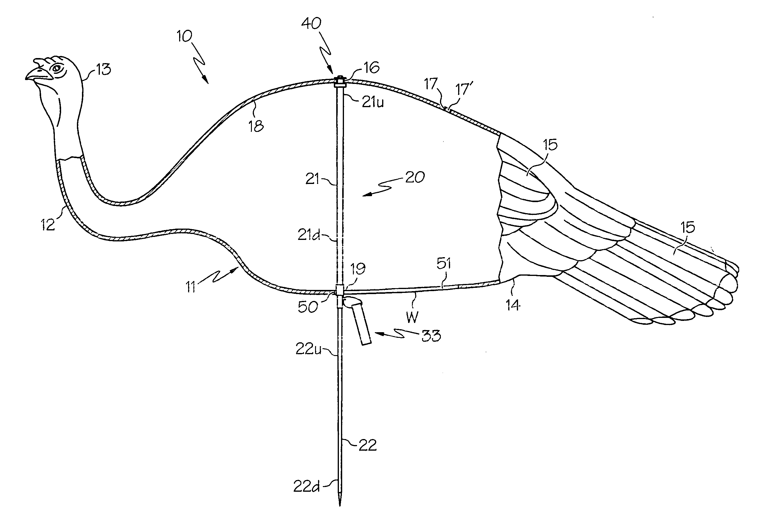
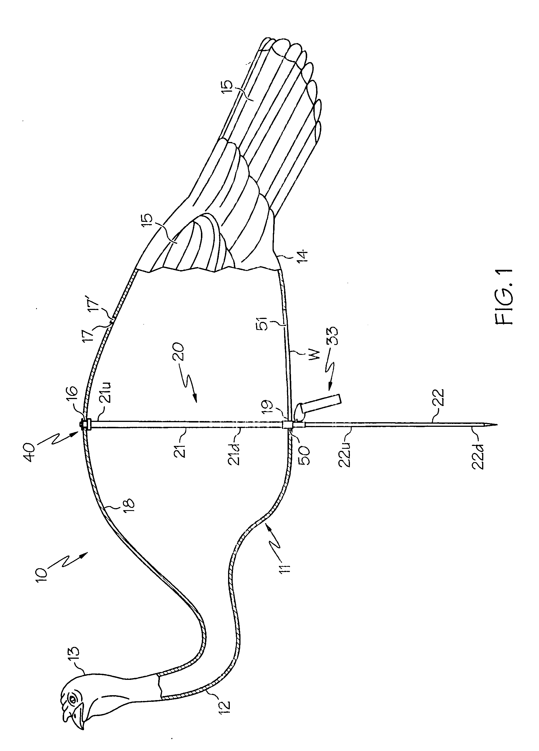
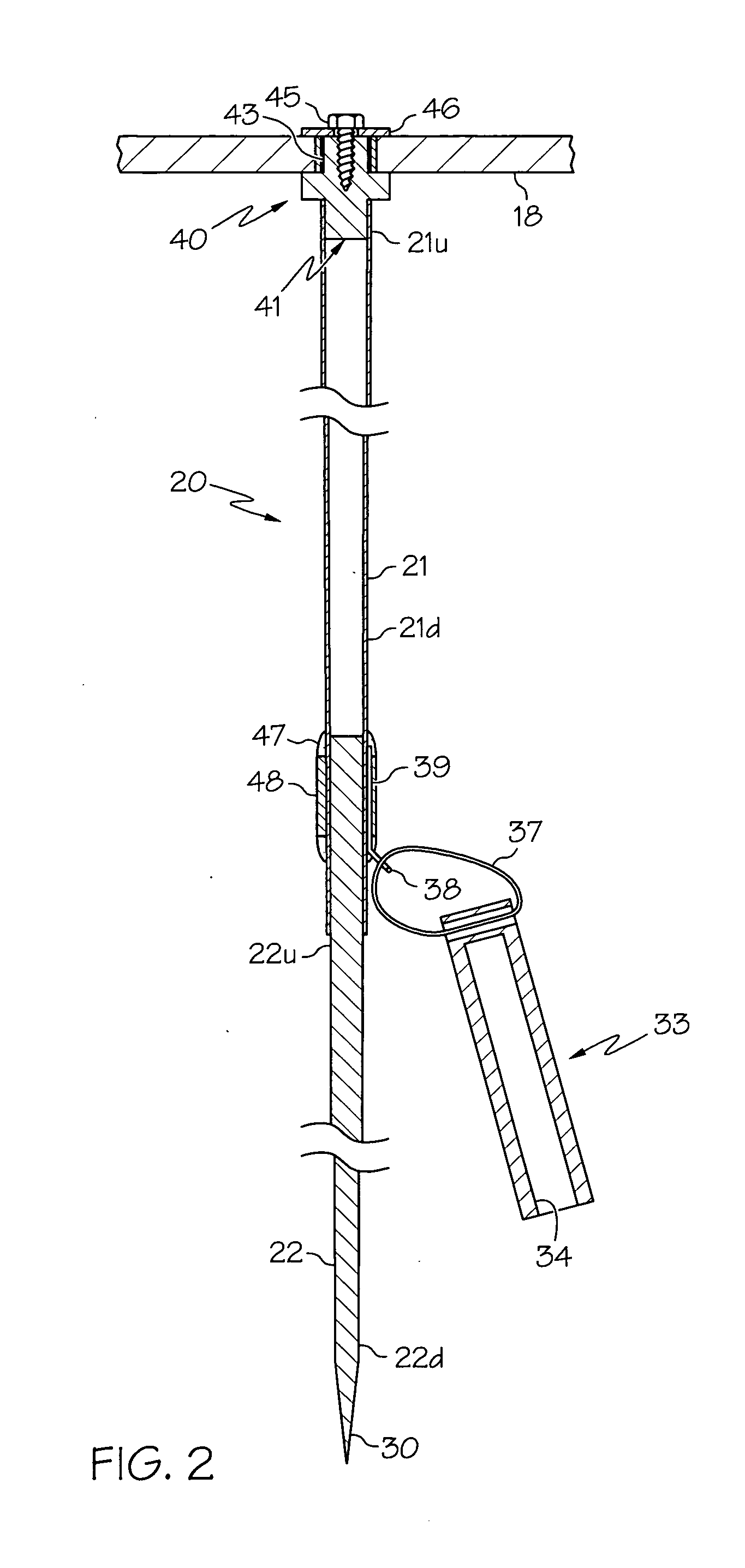
[0030]Secured within the body 11, about the midpoint between the base of the neck 12 and the tail 14, is a strut assembly generally referred to by reference numeral 20, having telescoped upper and lower struts 21 and 22 respectively. The strut assembly 20 is thrust, tubular upper strut 21 first, through lower body strut aperture 19 in the lower portion of the body. The diameter of the aperture 19 is large enough to allow upper portion 21u to pass through the aperture 19. The location of the aperture 19 is such that when the upper portion 21u of the upper strut 21 is secured in one of the donut washers 16 or 17 and the lower strut 21 is extended, the decoy resembles a live bird standing on its legs.

[0031]The lower strut 22 of the assembly 20 is preferably tubular (hence, lower or “inner” tube) because it is typically more economical to produce than a solid lower strut. The lower strut 22 is downwardly tapered so that the outside diameter of its upper portion 22u (see FIG. 2) near its...

second embodiment

[0041]Referring to FIG. 6, there is schematically illustrated the telescopable strut assembly 60 in cross-section, with the intermediate portions of the upper and lower struts broken away, secured in a donut washer (not shown, for clarity) of the upper wall 18 of the decoy. As before, the strut assembly 60 is thrust, upper (outer) tubular strut 61 first, through lower body strut aperture 19 which is large enough to allow upper strut 61u to pass through the aperture 19. Length of lower (inner) strut 62 is preferably greater than 85 percent of the length of the upper strut 61 (>0.85 the length of upper strut 61) so that the inner strut 62 may be concealed within the outer strut 61 when the lower end 61d of the upper strut 61 is fitted with a snugly fitting cap 80.

[0042]Analogous to the assembly described hereinabove, the lower strut 62 is downwardly tapered so that the outside diameter of its upper portion 62u near its upper end is greater than the outside diameter of its lower portio...


PUM


Abstract

A turkey decoy comprises a mass-producable synthetic resinous body adapted to be deployed in either a sentry or feeding position, with a telescopable assembly of rigid, that is, essentially inflexible, upper and lower struts, the upper necessarily being tubular, and the lower being either tubular or solid. The upper strut is removably securely fixed in an aperture in the upper surface of the decoy's body. Typically, the strut assembly is pre-assembled in the decoy so that neither strut in the assembly is detachable relative to the other. The strut assembly of non-detachably assembled struts, which assembly is secured in the decoy long before the decoy is to be deployed, allows a hunter to transport the pre-assembled decoy to the desired site in the poor light of the pre-dawn hours, unfold the decoy, pull the inner strut out until it locks in the outer strut, and thrust the pointed end into the ground. There is no assembly of the strut on site, no searching for the desired aperture in the dark.

Description

BACKGROUND OF THE INVENTION[0001]1. Field of the Invention[0002]This invention relates to a decoy apparatus for use by a hunter for wild fowl, in particular, large birds such as turkeys and geese. The invention comprises an improvement in means for easily and quickly anchoring the decoy with a strut through the middle of its body. The assembly comprises two essentially rigid struts, the inner strut being nearly completely concealed within the outer strut. By “essentially rigid strut” is meant that each strut resists deformation upon compression so that the inner strut, when manually grasped, may be thrust into the ground without fracturing it. The outer strut necessarily includes a longitudinal bore, that is, it is tubular; the inner strut may be either tubular or solid. When the decoy is deployed in a standing position by anchoring it in the ground with the strut assembly, the outer tubular strut is the upper strut and the inner strut is the lower strut. When the decoy is anchored,...

Claims


Application Information

Patent Timeline
IPC IPC(8): A01M31/06F16M13/00
CPCA01M31/06F16M11/08F16M13/022F16M11/28
Inventor SLOOP, STEPHEN S.
Owner SLOOP STEPHEN S
Why Eureka
Try Eureka