Masonry with steel reinforcement strip having spacers

a technology of steel reinforcement strips and spacers, which is applied in the field of masonry, can solve the problems of high tensile force of longitudinal rods or wires, fracture of mortar joints, and inability to absorb high tensile forces

Active Publication Date: 2011-11-24
NV BEKAERT SA
View PDF6 Cites 2 Cited by
  • Summary
  • Abstract
  • Description
  • Claims
  • Application Information

AI Technical Summary

Benefits of technology

[0014]It is clear, that in this way, the straight reinforcement wires are not weakened by any deformation operation and maintain their full tensile strength along their whole length.

Problems solved by technology

A disadvantage of this solution according to the U.S. Pat. No. 6,629,393 B2 is, that the bent longitudinal rods or wires are not able to take up high tensile forces because the rods are weakened by these bent deformations and can only take up the applied tensile forces after the bent portions are sufficiently straightened.
This straightening of the bent portions in the mortar joint will normally lead to fractures of the mortar joint.

Method used


Image

  • Masonry with steel reinforcement strip having spacers
  • Masonry with steel reinforcement strip having spacers
  • Masonry with steel reinforcement strip having spacers

Examples


Embodiment Construction

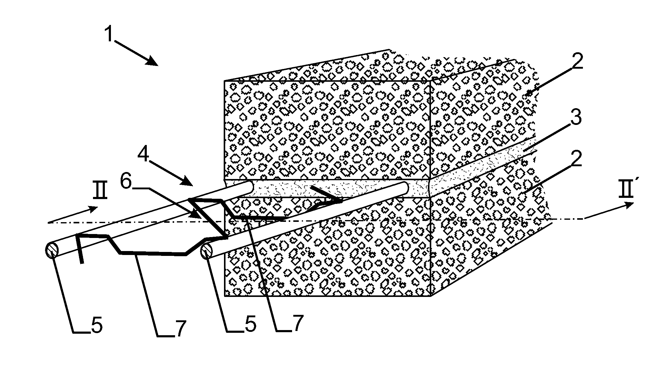
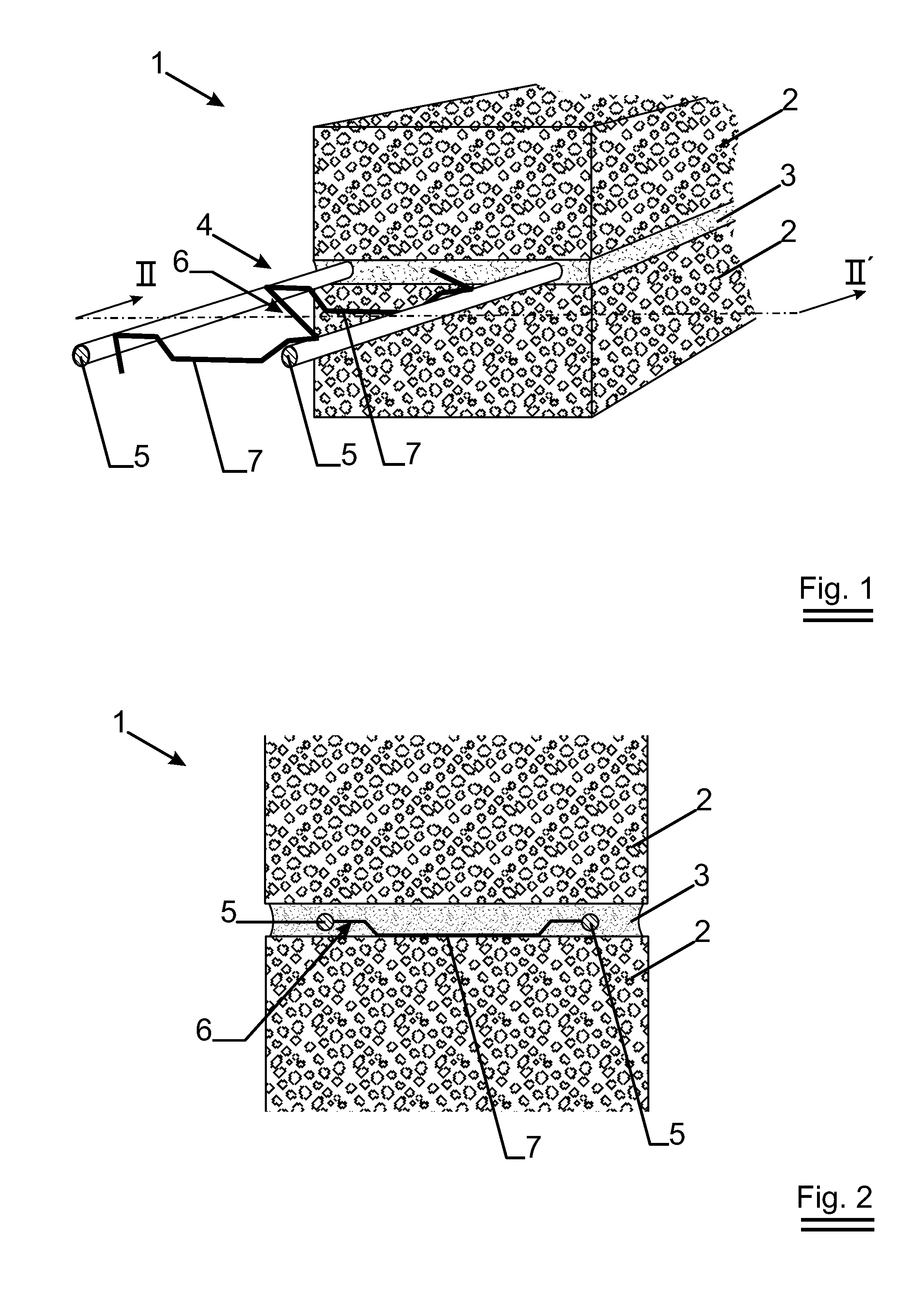
[0036]FIG. 1 shows a perspective view of a small part of a masonry 1 comprising two adjacent layers 2 of bricks and an intermediate joint 3 of mortar or another adhesive. The joint 3 is reinforced by means of a reinforcement strip 4.

[0037]The reinforcement strip, as shown in FIG. 1, comprises two straight, continuous, substantially parallel, steel reinforcement wires 5, which are welded to each other by means of a steel wire connecting structure 6. This shown steel wire connecting structure 6 runs between the two reinforcement wires 5 along a substantially zig-zag line. Such a steel wire reinforcement strip is e.g. described in the U.S. Pat. Nos. 2,300,181 and 3,183,628. Such a steel wire reinforcement strip is called a truss type. It is possible to replace this steel wire connecting structure 6 with a zig-zag form by a steel wire connecting structure in the form of a series of cross members, as described in the U.S. Pat. Nos. 2,929,238 and 6,629,393 B2. Such a steel wire reinforcem...


PUM

PropertyMeasurementUnit
distanceaaaaaaaaaa
distanceaaaaaaaaaa
distanceaaaaaaaaaa

Abstract

Masonry (1) comprising layers (2) of bricks and mortar joints (3), whereby at least one mortar joint (3) is reinforced by a reinforcement strip (4), whereby said strip (4) comprises at least two straight, continuous, substantially parallel, steel reinforcement wires (5), which are welded or glued to each other by means of a steel wire connecting structure (6), characterised in that the wire connecting structure (6) is provided with protuberances (7) protruding from the plane comprising said at least two straight reinforcement wires (5) and forming spacing elements (7) which keep the at least two straight reinforcement wires (5) at a specific distance from the layer (2) of bricks below and/or the layer (2) of bricks above said reinforcement strip (4).

Description

TECHNICAL FIELD [0001]This invention relates to a masonry comprising layers of bricks or building stones and mortar joints, whereby at least one mortar joint is reinforced by a reinforcement strip, whereby said strip comprises at least two straight, continuous, substantially parallel, steel reinforcement wires, which are connected to each other by means of a steel wire connecting structure.BACKGROUND ART [0002]Such a masonry is already known from the U.S. Pat. Nos. 2,300,181, 2,929,238 and 3,183,628.[0003]The correct application of adjacent layers of bricks, mortar joints and reinforcement strips in the mortar joints results in a masonry which can take up high tensile forces and shear forces compared with a masonry without reinforcement strips.[0004]An important condition for obtaining a correct construction of such a masonry is the necessity of obtaining a good adherence between the reinforcement wires of the reinforcement strip and the mortar joints, as is clearly described in the...

Claims


Application Information

Patent Timeline
Patent Type & Authority Applications(United States)
IPC IPC(8): E04B2/30E04B1/41
CPCE04B2/02E04C5/065E04B2002/0282E04G21/1883
Inventor VITT, GERHARDLAMBRECHTS, ANNTIMPERMAN, LEOPOLD
Owner NV BEKAERT SA
Why Eureka
Try Eureka