
Arrestor

a technology of reversing and reversing shafts, applied in the field of reversing, can solve the problems of failure of the system, complete coupling between the drive shaft and the output shaft, and no longer providing the desired output rotation, so as to reduce the length of the pin, the effect of modifying the characteristics of the system

Inactive Publication Date: 2011-11-24
CORCOST LTD
View PDF32 Cites 0 Cited by
  • Summary
  • Abstract
  • Description
  • Claims
  • Application Information

AI Technical Summary

Benefits of technology

[0018]The present invention prevents a rotating system from outputting in the event of such failures occurring by providing a system which permits the rotation of the output shaft when functioning correctly but which prevents the rotating system rotating and providing output when a failure occurs within the system.
[0019]The present invention provides a system providing rotary output when the movement of the pin is synchronised with the rotation of the output shaft but which will be prevented from providing a rotary output in the event of a failure as the pin will not move along the guideway as the movement of the pin will not be synchronised with the rotation of the output shaft resulting in the system not providing an output due to the abutment of the pin against the sidewall of the guideway. Therefore, the present invention provides a rotary system with a system which can prevent rotary output when there is a failure in the rotary system such that it would not be providing a desired / expected output.
[0026]Preferably, the pin projects into / through a guide which is generally aligned with the pin path. The guide is fixed with respect to the pin path and may be integral with a casing housing the system. The guide acts to guide the pin along its pin path, as well as helping to prevent the pin from being moved out of the pin path, for example due to rotation of the output shaft. More specifically, where the output shaft is rotating but is not synchronised with the movement of the pin the side walls of the guideway of the output shaft will abut against the pin. The moment carried by the output shaft may be relatively large such that it imposes a force on the pin. The guides reduce the unsupported length of the pin and hence allow a smaller pin to be used and share the load with the casing. Further, the use of guides allows the characteristics of the system to be altered, and assists in isolating load and helps prevent the applied force from the output shaft from being transmitted to the connection between the pin and the arrestor path.
[0030]Where the system includes one or more arrestor paths, components of the system may be shared between arrestor paths. Sharing of components can minimise the complexity of the system as well as reducing cost and spacing requirements. However in some cases, it may be preferable for components of the system to be separately provided for each arrestor path. For example, where the system includes a self-locking means, it may be preferable for each arrestor path to be separately provided with a self-locking means. This has the advantage that if a self-locking means in one arrestor path becomes damaged such that in the event of a failure in the system the self-locking means cannot self-lock, then the self-locking means in the other arrestor path(s) can still self-lock and therefore prevent the pin from moving, and therefore prevent the undesired rotation of the output shaft.

Problems solved by technology

However, over time, failures can occur in the system such that it no longer provides a desired output rotation.
For example, a catastrophic failure could occur in the system such that the coupling between the drive shaft and the output shaft is completely severed.
Alternatively, failure in the system could occur due to the components becoming damaged and / or worn and no longer functioning as expected.
Such damage and / or wear can affect the relationship between the rotation of the drive shaft and the rotation of the output shaft, and can therefore result in discrepancies occurring between the actual output provided by the system and the output which would normally be expected.
In both cases such a failure may be undesirable.
For example, where the rotating system is being used to raise or lower objects which are fragile and / or valuable, sudden movement of the objects by an unexpected / undesired amount could result in damage of the objects.

Method used


Image

  • Arrestor
  • Arrestor
  • Arrestor

Examples


first embodiment

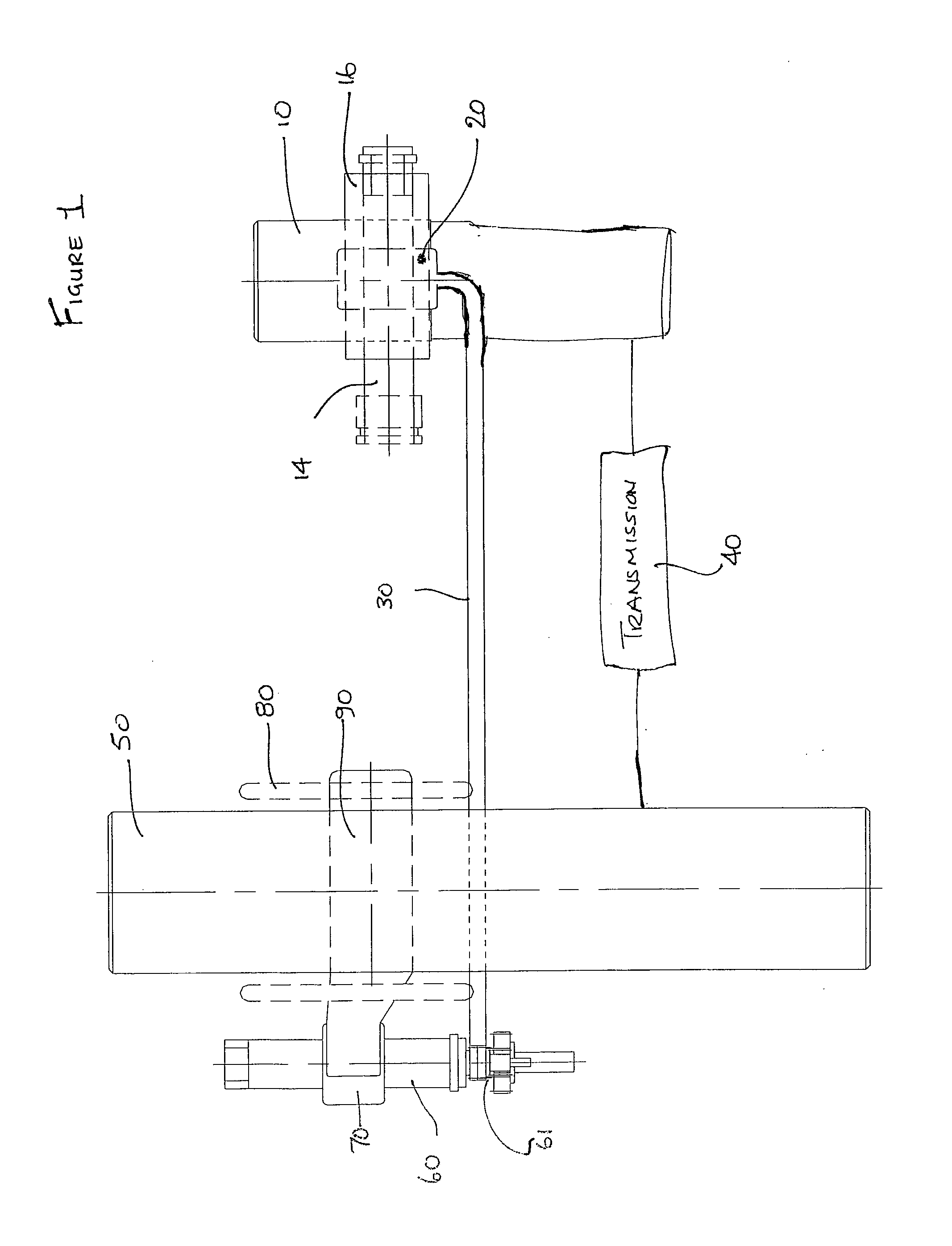
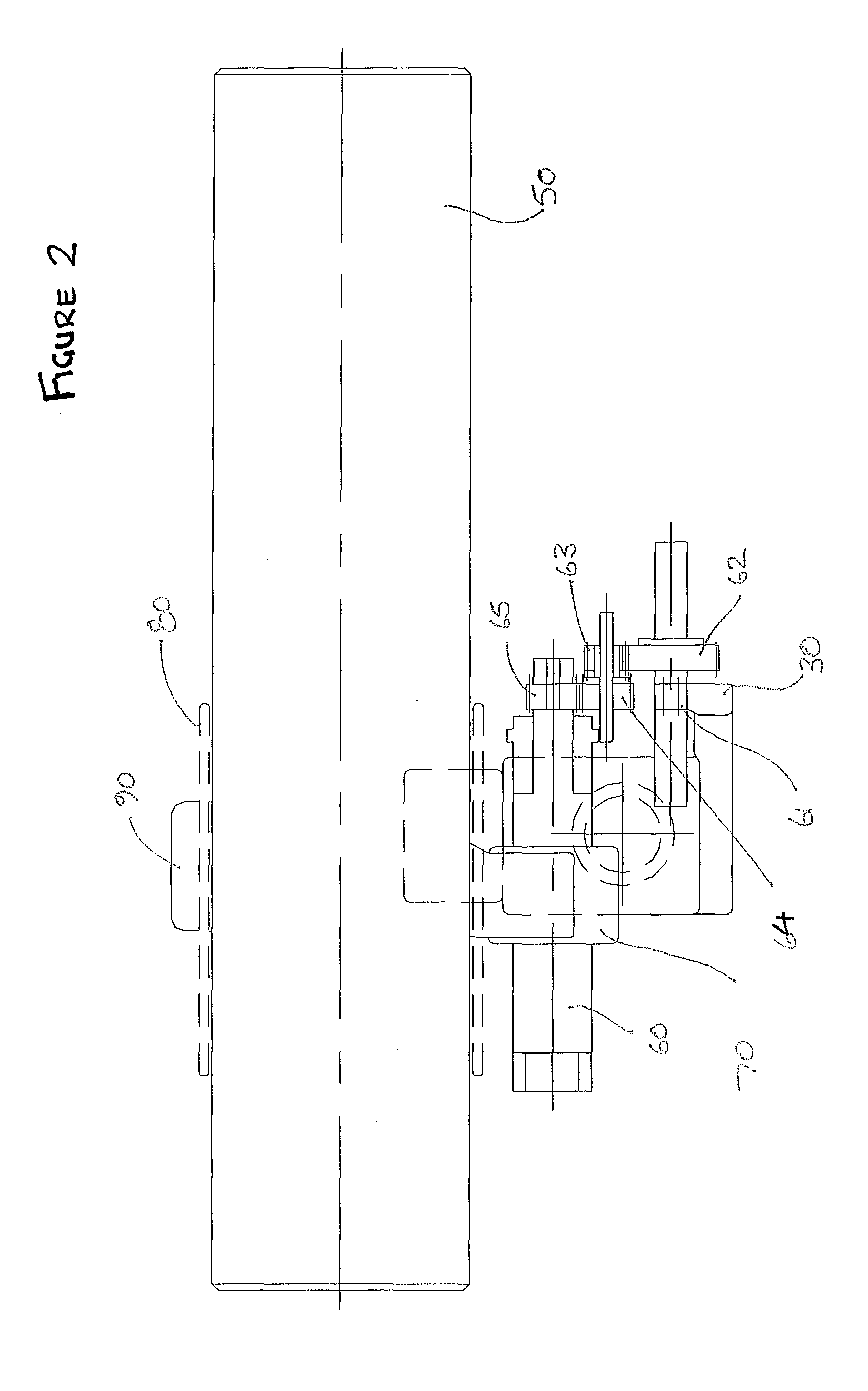
[0049]FIG. 1 shows a schematic view of a system having a rotary output. FIG. 2 shows the system of FIG. 1 when viewed from the left hand side of FIG. 1. FIG. 3 shows the system of FIG. 1 when viewed from the lower side of FIG. 1.

[0050]In the first embodiment, there is a transmission path coupling a drive shaft 10 to an output shaft 50, via a transmission means 40. As shown in FIG. 1, the transmission means 40 is coupled to both the drive shaft 10 and the output shaft 50 such that rotation of the drive shaft 10 results in a proportional rotation of the output shaft 50. The transmission means 40 can be any arrangement of gears or other suitable components which can transmit the motion and force of the drive shaft 10 to the output shaft 50. The transmission means 40 can convert and / or modify the motion and force transmitted from the drive shaft 10 and apply that modified motion to the output shaft 50 as desired.

[0051]As can be seen in FIGS. 1 to 3, in addition to the transmission path,...

second embodiment

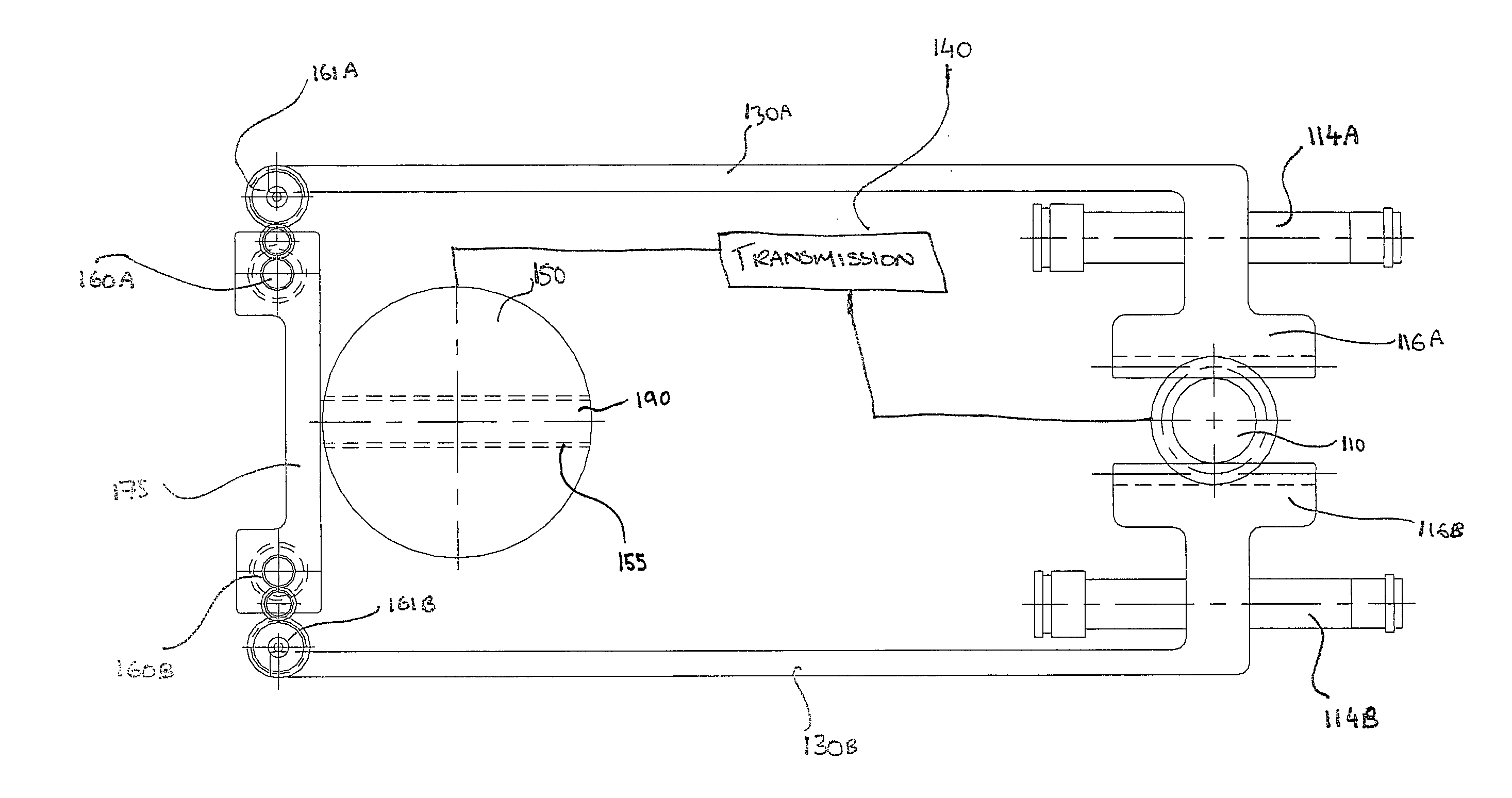
[0068]FIG. 4 shows a schematic view of a system having a rotary output. The rotating system shown is similar to that shown in FIG. 1, but with the notable exception that the system of FIG. 4 includes a second arrestor path.

[0069]More specifically, the drive shaft 110 is meshed with and rotated with respect to first and second toothed sections 116A, 116B. The first and second toothed sections 116A, 116B are integral with or attached to respective first and second extension arms 130A, 130B, which are in turn meshed with respective first and second gears 161A, 161B. The first gear 161A is coupled, via a series of gears, to a first leadscrew 160A, which is in turn meshed with a first nut 170A. The second gear 161B is coupled, via a series of gears, to a second leadscrew 160B, which is in turn meshed with a second nut 170B. However, it will be appreciated that the first and second gears 161A, 161B may instead be located at one end of their respective leadscrews 160A, 160B without needing...

fourth embodiment

[0080]FIG. 7 shows a side view of a system having a rotary output. In this embodiment the guideway is a channel 455 extending through the output shaft 450. The pin 490 projects completely through the channel 455 in the output shaft 450, and is attached to or integral with a first nut 470A at its first end 491A, and attached to or integral with a second nut 470B at its second end 491B. Each nut 470A, 470B is meshed with its own respective leadscrew 460A, 460B. Each end of the pin 491A, 491B is coupled to the drive shaft 410 by a different arrestor path. Namely, the first end of the pin 491A is coupled to the drive shaft 410 via the first arrestor path, and the second end of the pin 491B is coupled to the drive shaft 410 via the second arrestor path, such that rotation of the drive shaft 410 results in movement of each end of the pin 490.

[0081]In order for the system to provide an expected rotary output, the movement of both ends of the pin 491A, 491B must be synchronised with the rot...


PUM


Abstract

A system having a rotary output, including a drive shaft, a pin coupled to the drive shaft and an output shaft coupled to the drive shaft. A guideway is associated with the output shaft. Rotation of the drive shaft results in rotation of the output shaft and the guideway and movement of the pin along a pin path. The system is prevented from providing a rotary output when the pin abuts against a sidewall of the guideway, but permitted to provide a rotary output when the portion of the guideway aligned with the pin path corresponds with the position of the pin.

Description

BACKGROUND OF THE INVENTION[0001]Rotating systems have been used for many years and can be applied to a wide range of situations. In general, rotating systems comprise a rotating drive component, a rotating output component and a transmission means for providing transmission between the drive component and the output component. The transmission means can be arranged to convert and / or modify the motion of the drive component and apply that modified motion to the output component depending upon what output is desired.[0002]Various fail-safe mechanisms have been proposed to prevent a rotating system from rotating under certain conditions.[0003]For example, a ratchet arrangement can be used to prevent a system from rotating in a backwards direction. Ratchet arrangements generally consist of a circular rotating gear having a rack of teeth running around its circumference and a pivoting finger that engages with the teeth. The teeth are shaped to have a steep side and a gently sloping side...

Claims


Application Information

Patent Timeline
Patent Type & Authority Applications(United States)
IPC IPC(8): F16D11/14
CPCA61G5/1056A61G7/018F16H19/04F16H25/20Y10T74/18576Y10T74/20018Y10T74/2014Y10T74/2003Y10T74/19565
Inventor CORCORAN, STEVEN
Owner CORCOST LTD
Learn More