Synchrotron power supply apparatus and method of use thereof

Inactive Publication Date: 2011-11-24
BALAKIN ANDREY VLADIMIROVICH +1
View PDF8 Cites 25 Cited by
  • Summary
  • Abstract
  • Description
  • Claims
  • Application Information

AI Technical Summary

Problems solved by technology

These particles damage the DNA of cells, ultimately causing their death.
Cancerous cells, because of their high rat

Method used


Image

  • Synchrotron power supply apparatus and method of use thereof
  • Synchrotron power supply apparatus and method of use thereof
  • Synchrotron power supply apparatus and method of use thereof

Examples


Embodiment Construction

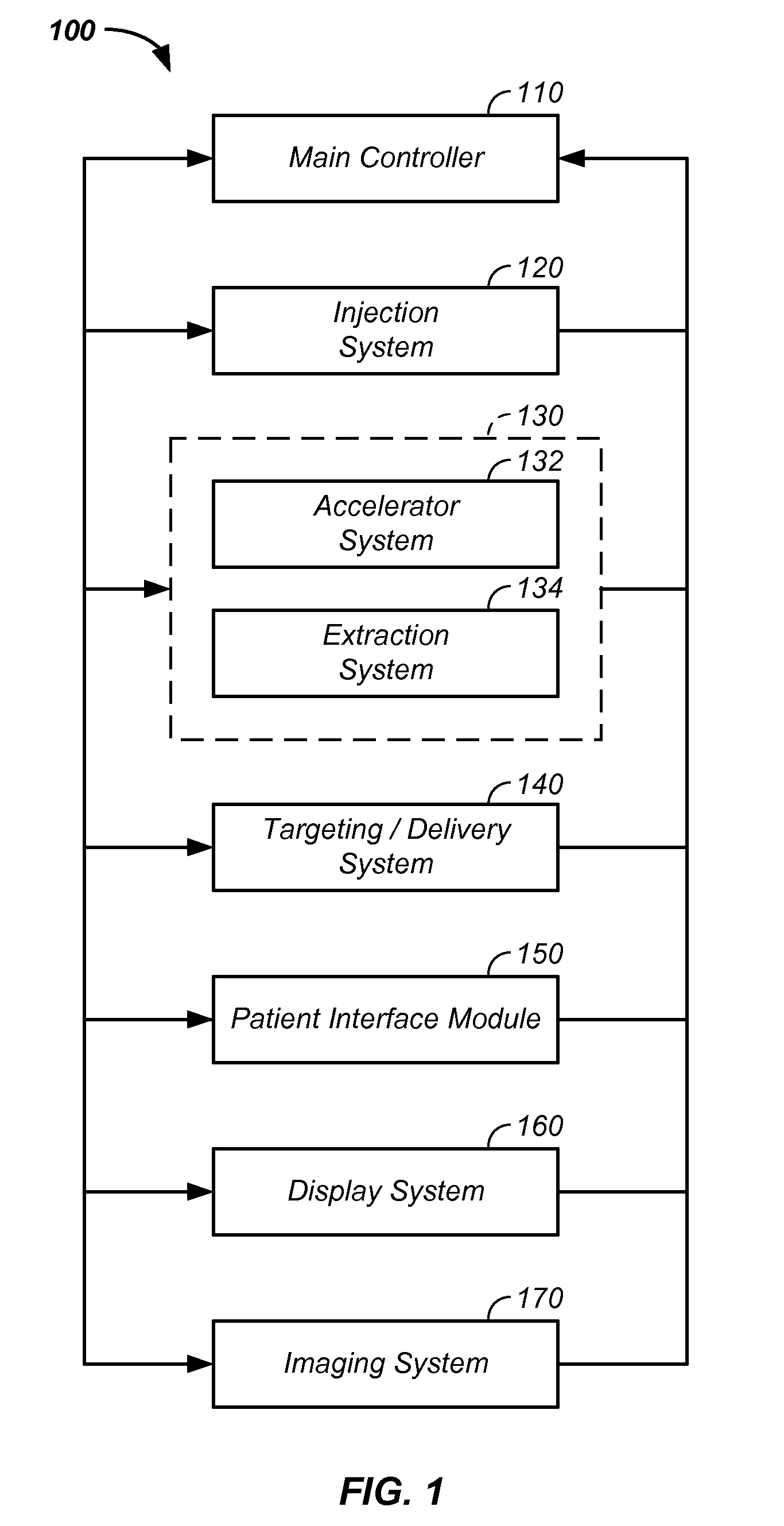
[0107]The invention comprises a method and apparatus to enhance performance of acceleration of charged particles in a charged particle cancer therapy system.

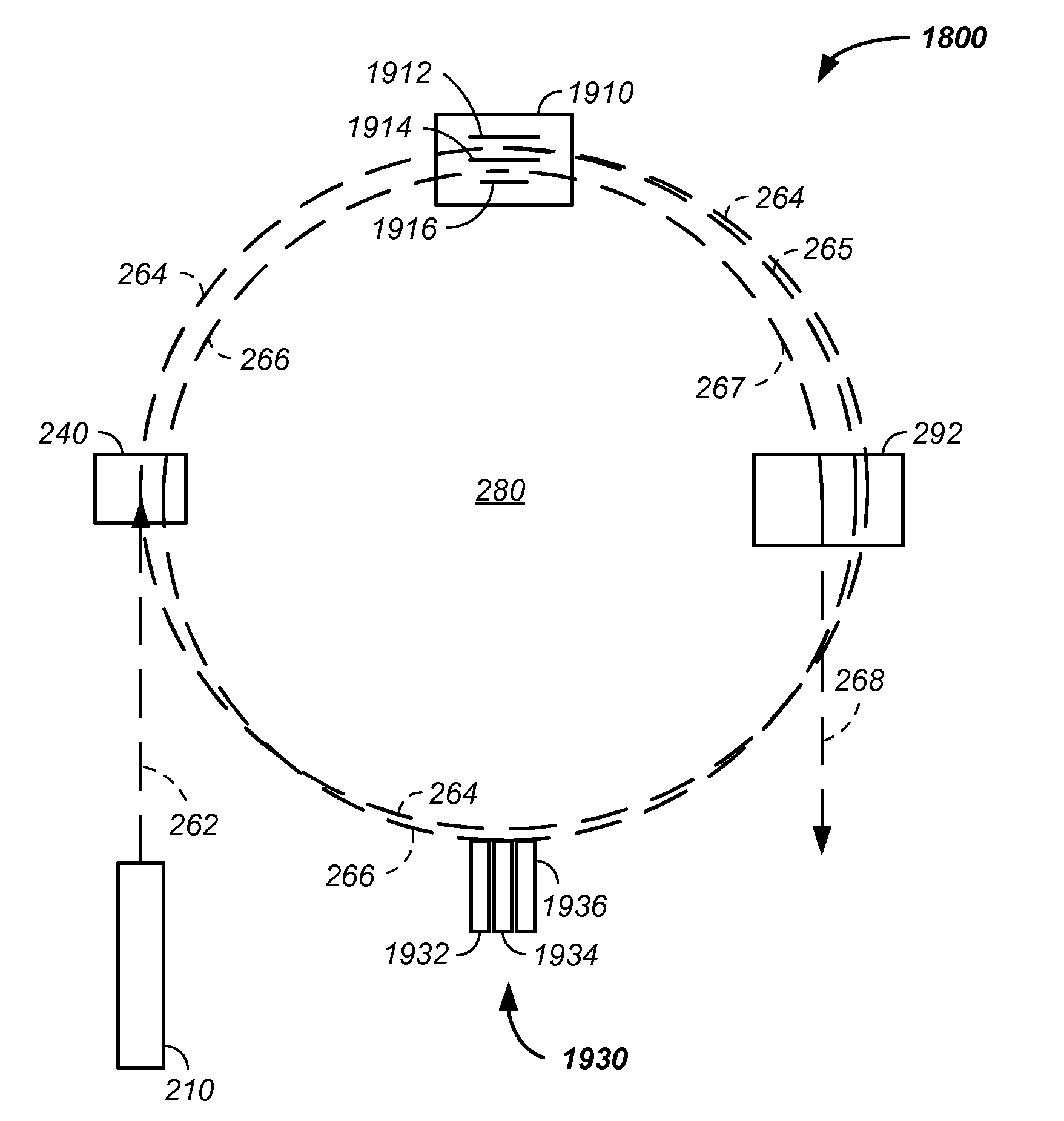
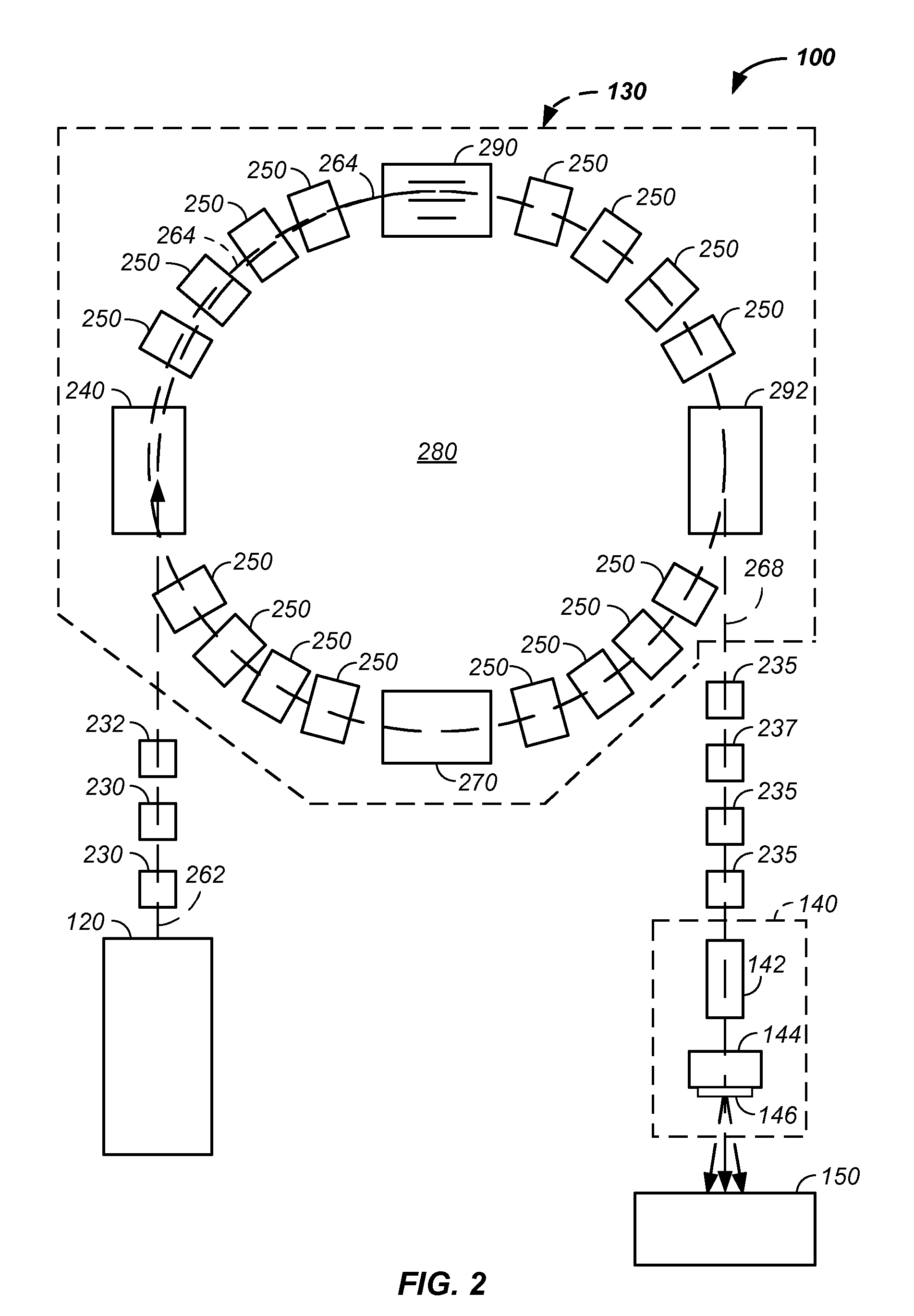
[0108]In one embodiment, a single power supply is electrically connected to a plurality of magnet sections to provide a uniform current to a plurality of magnets at a given period in time.

[0109]In another embodiment, one or more switches are used to introduce a corresponding one or more resistors into a circuit linking a power supply to a magnet and / or an inductor during a recovery phase between acceleration cycles of a synchrotron. For example, a charged particle cancer therapy system or synchrotron system uses one or more switches to introduce a corresponding one or more resistors into a circuit linking a power supply to a magnet or an inductor during an applied power recovery phase between acceleration cycles of the synchrotron, which reduces time of reduction in power from an active applied power to a power suitable for use ...


PUM


Abstract

The invention comprises a charged particle cancer therapy system or synchrotron system using a single power supply electrically connected to a plurality of magnet sections to provide a uniform current to a plurality of magnets at a given period in time. Optionally, one or more switches introduce a corresponding one or more resistors into a circuit linking the power supply to a magnet or an inductor during an applied power recovery phase between acceleration cycles of the synchrotron, which reduces time of reduction in power from an active applied power to a power suitable for use with a subsequent injection of charged particles into the synchrotron.

Description

CROSS-REFERENCES TO RELATED APPLICATIONS[0001]This application:[0002]is a continuation-in-part of U.S. patent application Ser. No. 12 / 425,683 filed Apr. 17, 2009, which claims the benefit of:[0003]U.S. provisional patent application No. 61 / 055,395 filed May 22, 2008, now U.S. Pat. No. 7,939,809 B2;[0004]U.S. provisional patent application No. 61 / 137,574 filed Aug. 1, 2008;[0005]U.S. provisional patent application No. 61 / 192,245 filed Sep.[0006]17, 2008;[0007]U.S. provisional patent application No. 61 / 055,409 filed May 22, 2008;[0008]U.S. provisional patent application No. 61 / 203,308 filed Dec. 22, 2008;[0009]U.S. provisional patent application No. 61 / 188,407 filed Aug. 11, 2008;[0010]U.S. provisional patent application No. 61 / 188,406 filed Aug. 11, 2008;[0011]U.S. provisional patent application No. 61 / 189,815 filed Aug. 25, 2008;[0012]U.S. provisional patent application No. 61 / 201,731 filed Dec. 15, 2008;[0013]U.S. provisional patent application No. 61 / 205,362 filed Jan. 12, 2009;[0...

Claims


Application Information

Patent Timeline
IPC IPC(8): H01J3/14H05H13/04
CPCA61N5/10H05H13/04H05H7/10A61N2005/1087
Inventor BALAKIN, VLADIMIR
Owner BALAKIN ANDREY VLADIMIROVICH
Why Eureka
Try Eureka