
Method for identifying a sequence of input signals

Inactive Publication Date: 2011-11-24
ROBERT BOSCH GMBH
View PDF3 Cites 4 Cited by
  • Summary
  • Abstract
  • Description
  • Claims
  • Application Information

AI Technical Summary

Benefits of technology

[0003]The method according to the present invention according to Claim 1 has the advantage over the related art that the reference time is set automatically as a function of the time characteristic of the input signals and thus, on the one hand, a considerably faster response time and, on the other hand, an adaption of the input signal evaluation to the individual usage behavior of an input signal producer, for example a human user or a sensor controlled by the human user, is achieved. This is achieved by determining the response time for future consecutive input signals which “belong together” as a function of the time interval between the first input signal and the second input signal, so that a predefined response time must be assumed only between the first two input signals, which is adapted as early as in the following step to the time characteristic of the input signals. Thus, in the case of a user who, for example, performs double clicks relatively slowly, a longer response time is automatically set, while in the case of a user who performs the exemplary double clicks more rapidly, a correspondingly shorter response time is set. This is advantageous in particular if a distinction not only between a single input signal and a double input signal is to be achieved, but also when greater input signal sequences such as triple input signals, quadruple input signals, quintuple input signal, etc., are to be identified. In the case of N-fold input signals, the adaption of the response time after the second input signal is adapted for all subsequent further (N−2) input signals. In this case, the method according to the present invention also allows a considerable reduction of the response time to be achieved, since the time savings is equal to the product of the difference between the predefined response time and the adapted response time and the factor (N−2). Because the time until the arrival of the next input signal is “anticipated” by the method, it is also possible to filter out false input signals and thus to increase the accuracy of the identification of input signals. This is achieved in that, on the one hand, the adapted reference value is set equal to the time interval and, on the other hand, a tolerance range is set around the reference value in which the further input signal must arrive in order to be identified. As defined by the present invention, setting the reference time as a function of the time interval includes, in particular, that the reference time is equal to the sum of the value of the time interval and a tolerance value. The tolerance value includes in particular a constant and increases the adapted reference value by a relatively small amount; thus small differences in the time characteristic of the input signal are also detected.
[0011]According to another preferred refinement, it is provided that the identification of an input signal is performed only when the signal amplitude of the input signal exceeds a signal threshold value and / or only when the signal length of the input signal exceeds a time threshold value. In a particularly advantageous manner, the input signal thus must have a certain signal height and / or a certain signal width for the identification of the input signal, so that the risk of misidentification due to false signals, for example due to external interference such as interfering radiation, vibrations, etc., is reduced.
[0012]According to another preferred refinement, it is provided that, after the identification of an input signal, the system waits for a down time before a subsequent input signal is identifiable. Typically the input signals perform a relatively short post-pulse oscillation, so that there is the risk that such a post-pulse oscillation exceeds the signal threshold value and is identified as another input signal. By waiting for the down time during which the post-pulse oscillations decay without identification, the risk of misidentification due to post-pulse oscillations is advantageously reduced.

Problems solved by technology

The disadvantage of this method is that the reference time is a fixed constant, so that when the user who typically double clicks via two clicks rapidly following each other performs a simple click, the system must wait for the relatively long reference time before outputting the single-click signal.

Method used


Image

  • Method for identifying a sequence of input signals
  • Method for identifying a sequence of input signals
  • Method for identifying a sequence of input signals

Examples


Embodiment Construction

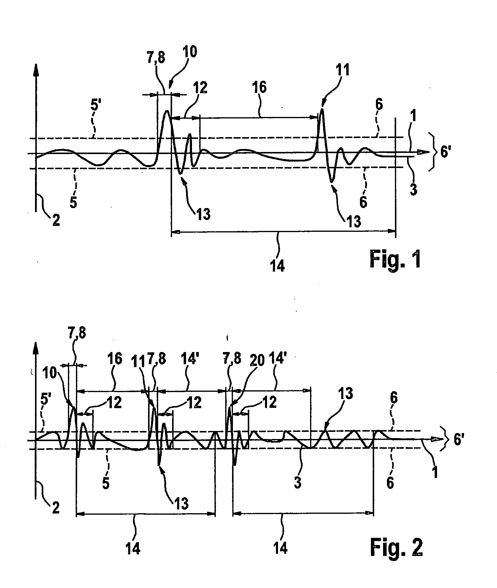
[0018]FIG. 1 shows a schematic view of a method according to a first specific embodiment of the present invention, a diagram having an abscissa 1 and an ordinate 2 being shown in FIG. 1; time is plotted on abscissa 1 and the amplitude is plotted on ordinate 2. Furthermore, in the diagram the amplitude of a signal 3 is plotted against time, signal 3 including, for example, an acceleration signal of an acceleration sensor (not illustrated), the acceleration signal including in particular the variation of an acceleration as a function of time. In the diagram, a signal threshold value 6, which has a constant value and defines a subthreshold range 6′ around abscissa 1, is shown in the form of two dashed lines 5, 5′. Signal 3 is identified only when the absolute value of signal 3 at a certain point in time is greater than the absolute value of signal threshold value 6 and consequently signal 3 is outside subthreshold range 6′. In addition, signal 3 must be outside subthreshold range 6′ fo...


PUM


Abstract

A method for identifying a sequence of input signals is proposed, a first input signal being identified in a first method step, a second input signal being identified within a predefined reference time in a second method step, and a time interval between the first input signal and the second input signal being determined in a third method step and furthermore the adapted reference time being set as a function of the time interval in a fourth method step.

Description

BACKGROUND INFORMATION[0001]The present invention is directed to a method for identifying a sequence of input signals according to the definition of the species of Claim 1.[0002]Such methods are generally known. For example, document DE 10 2004 001 226 A1 describes a method for identifying a double click, a first touch being detected using a key device in a first step, a second touch being detected using the key device in a second step, and a double-click signal being output in a third step if the sum of the durations of the first touch, the second touch, and the time interval between the first and second touches is less than a reference time. Thus, after the first touch, an identifying unit checks whether a second touch occurs within the reference time. In the case where no second touch occurs, the system waits for the entire reference time to elapse before a double-click signal may be ruled out. The disadvantage of this method is that the reference time is a fixed constant, so tha...

Claims


Application Information

Patent Timeline
IPC IPC(8): G06F3/01G06F3/038G06F3/041G06F3/048G06F3/0488
CPCG06F3/038G06F3/0488G06F3/0416G06F3/04166
Inventor SCHIFFERDECKER, DANIELSCHEIERMANN, SERGEJ
Owner ROBERT BOSCH GMBH
Learn More