Light source assembly mechanism for LED lamps

a technology of led lamps and assembly mechanisms, which is applied in the direction of lighting and heating apparatus, instruments, lighting support devices, etc., can solve the problems of inability to meet use requirements, inconvenient assembly, and inability to modularize the components of molds, etc., to achieve the effect of convenient assembly and better meeting use requirements

Active Publication Date: 2011-11-24
GREEN LIGHTING TECH CORP
View PDF2 Cites 45 Cited by
  • Summary
  • Abstract
  • Description
  • Claims
  • Application Information

AI Technical Summary

Benefits of technology

[0005]Therefore, the primary object of the present invention is to provide a light source assembly mechanism for an LED lamp that adopts modular design, can change light illumination angle and facilitate assembly, thus better meet use requirements.
[0009]Compared with the conventional techniques, the present invention provides many advantages, notably:
[0010]1. The invention adopts modular design, and hence it can save mold development cost, reduce the numbers of components, simplify assembly processes to lower production cost.

Problems solved by technology

However, the LED lamp tube replacing the traditional fluorescent lamp used for direct illumination, indirect illumination and illumination in low temperature does not have modular design.
As a result, mold development cost is higher, component composition is complex, and production cost is also higher.
All these make product prices too high, and hence product popularity suffers.
Moreover, the conventional LED lamp tube has a narrower light emission angle and unadjustable emission direction that limit its utilization.
Assembly flexibility is lower and more time-consuming, thus cannot meet use requirements.

Method used


Image

  • Light source assembly mechanism for LED lamps
  • Light source assembly mechanism for LED lamps
  • Light source assembly mechanism for LED lamps

Examples


Embodiment Construction

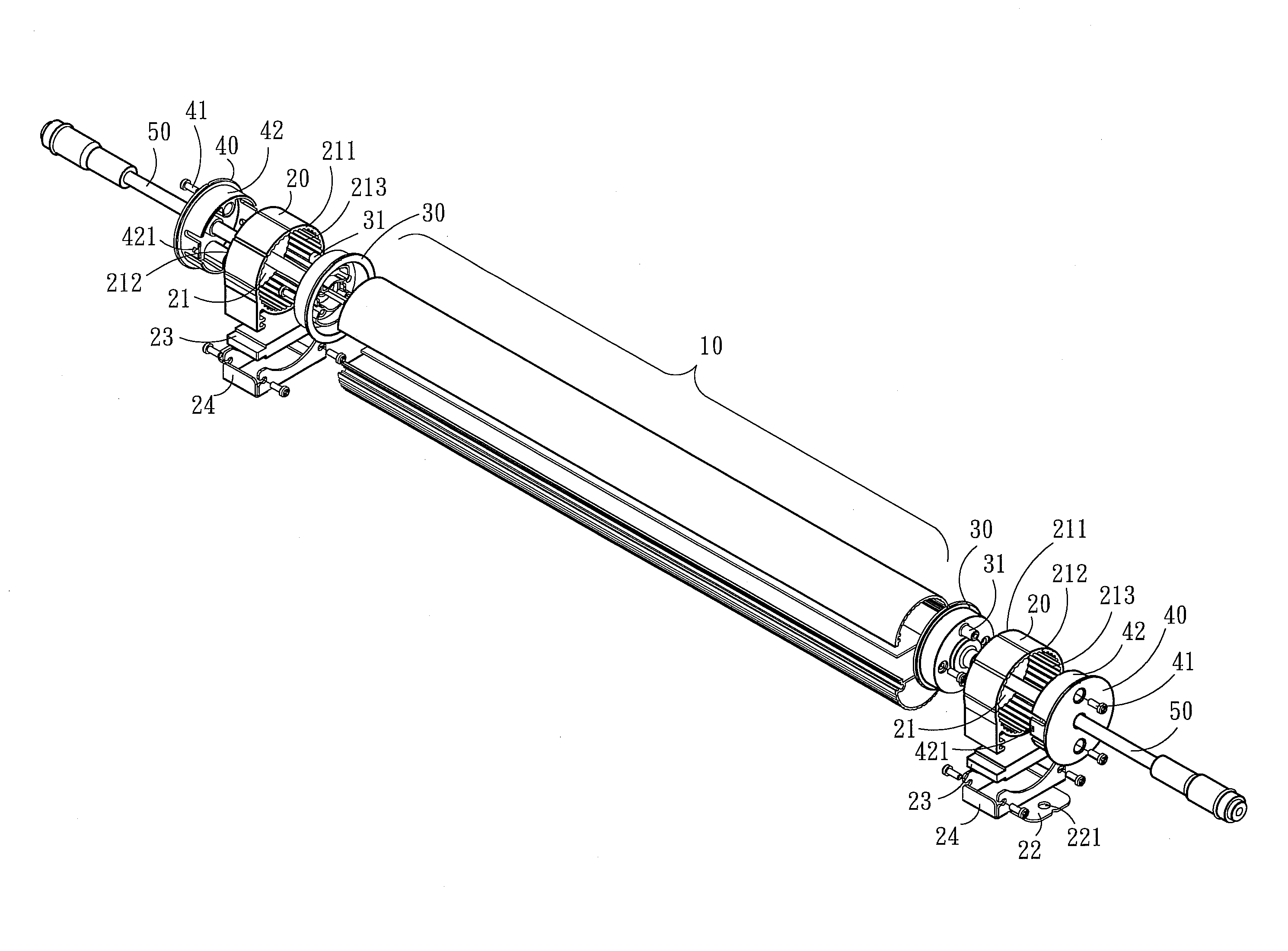
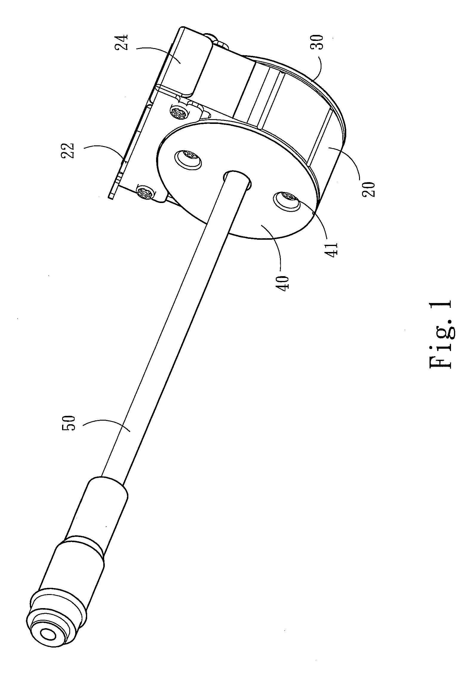
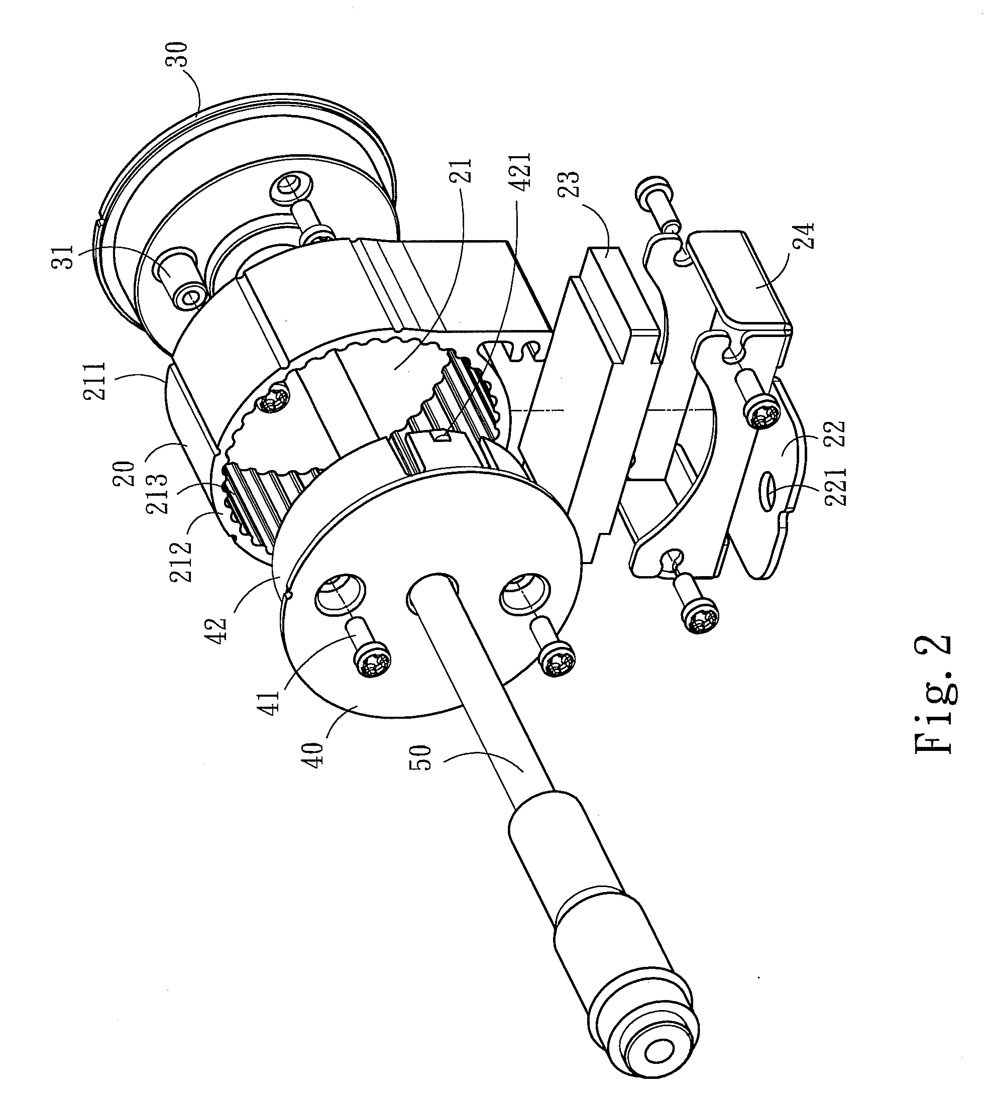
[0021]Please refer to FIGS. 1, 2 and 3, the present invention aims to provide a light source assembly mechanism which is installed at one end of an LED lamp tube 10. The light source assembly mechanism of the invention includes a base 20, a lamp tube side cap 30, a turning module side cap 40, and a turning rod 50. The base 20 has a housing chamber 21 formed in a cylindrical shape and communicating with two opposite sides thereof, and a first opening 211 and a second opening 212 at the two opposite sides thereof.

[0022]The lamp tube side cap 30 has one side fastened to one end of the LED lamp tube 10 and another side covering the first opening 211 and formed a fastening portion 31 which is held in the housing chamber 21. The turning module side cap 40 covers the second opening 212 and has a coupling portion 41 extended into the housing chamber 21 to fasten to the fastening portion 31. The turning rod 50 runs through the turning module side cap 40 and is fastened to the lamp tube side ...


PUM


Abstract

A light source assembly mechanism includes two sets installed at two ends of an LED lamp tube. Each light source assembly mechanism includes a base, a lamp tube side cap, a turning module side cap and a turning rod. The lamp tube side cap has one side fastened to one end of the LED lamp tube and another side running through the base via a fastening portion to fasten to a coupling portion formed on the turning module side cap. The turning rod runs through the turning module side cap to fasten to the lamp tube side cap. With the same modular elements used at two sides of the LED lamp tube, mold development cost can be reduced, and assembly processes can be simplified. Through turning the turning rod, illumination angle of the LED lamp tube can be adjusted to meet illumination requirements.

Description

FIELD OF THE INVENTION[0001]The present invention relates to an LED lamp light source and particularly to a light source assembly mechanism for an LED lamp.BACKGROUND OF THE INVENTION[0002]LED lamp light source provides many advantages in comparison with the traditional fluorescent lamp light source, such as power saving, greater illumination, higher efficiency and lower temperature and the like, and thus it gradually replaces the traditional fluorescent lamp and becomes the mainstream of illuminated light source.[0003]However, the LED lamp tube replacing the traditional fluorescent lamp used for direct illumination, indirect illumination and illumination in low temperature does not have modular design. As a result, mold development cost is higher, component composition is complex, and production cost is also higher. All these make product prices too high, and hence product popularity suffers.[0004]Moreover, the conventional LED lamp tube has a narrower light emission angle and unad...

Claims


Application Information

Patent Timeline
Patent Type & Authority Applications(United States)
IPC IPC(8): F21V15/01
CPCF21K9/30F21S4/008F21Y2103/003F21V21/30F21Y2101/02F21V21/096F21S4/28F21K9/20F21Y2103/10F21Y2115/10F21K9/65
Inventor CHEN, YU-WEN
Owner GREEN LIGHTING TECH CORP
Why Eureka
Try Eureka