
Adaptive Control for Transition Between Multiple Modulation Modes in a Switching Power Converter

a switching power converter and multiple modulation technology, applied in the direction of electric variable regulation, process and machine control, instruments, etc., can solve the problem of forming a control gap between the two control sections, and achieve the effect of fast transition between pwm and pfm modes and low output rippl

Active Publication Date: 2011-11-24
DIALOG SEMICONDUCTOR INC
View PDF8 Cites 28 Cited by
  • Summary
  • Abstract
  • Description
  • Claims
  • Application Information

AI Technical Summary

Benefits of technology

[0017]The present invention has the advantage that transition between PWM and PFM modes occurs fast, with low output ripple caused during the transition. No limitation needs to be imposed on the control voltage range in each of the PWM and PFM control sections, because the control parameters in the PWM and PFM control sections need not be matched to one another, due to the separation of the PWM and PFM modes by the control gap.

Problems solved by technology

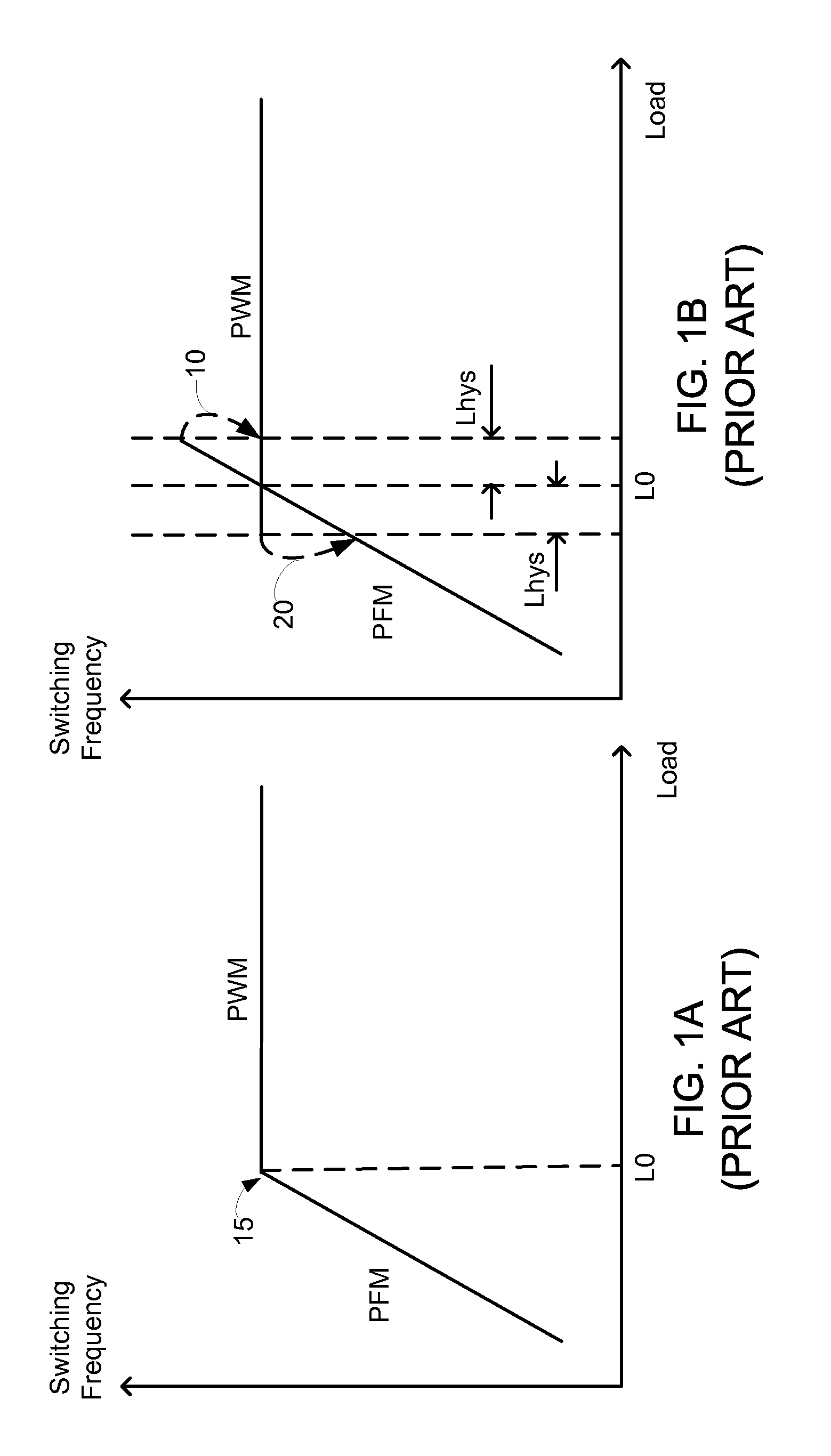
Each of the PWM and PFM modulation modes cannot operate continuously beyond its boundaries, thereby forming a control gap between the two control sections.

Method used


Image

  • Adaptive Control for Transition Between Multiple Modulation Modes in a Switching Power Converter
  • Adaptive Control for Transition Between Multiple Modulation Modes in a Switching Power Converter
  • Adaptive Control for Transition Between Multiple Modulation Modes in a Switching Power Converter

Examples


Embodiment Construction

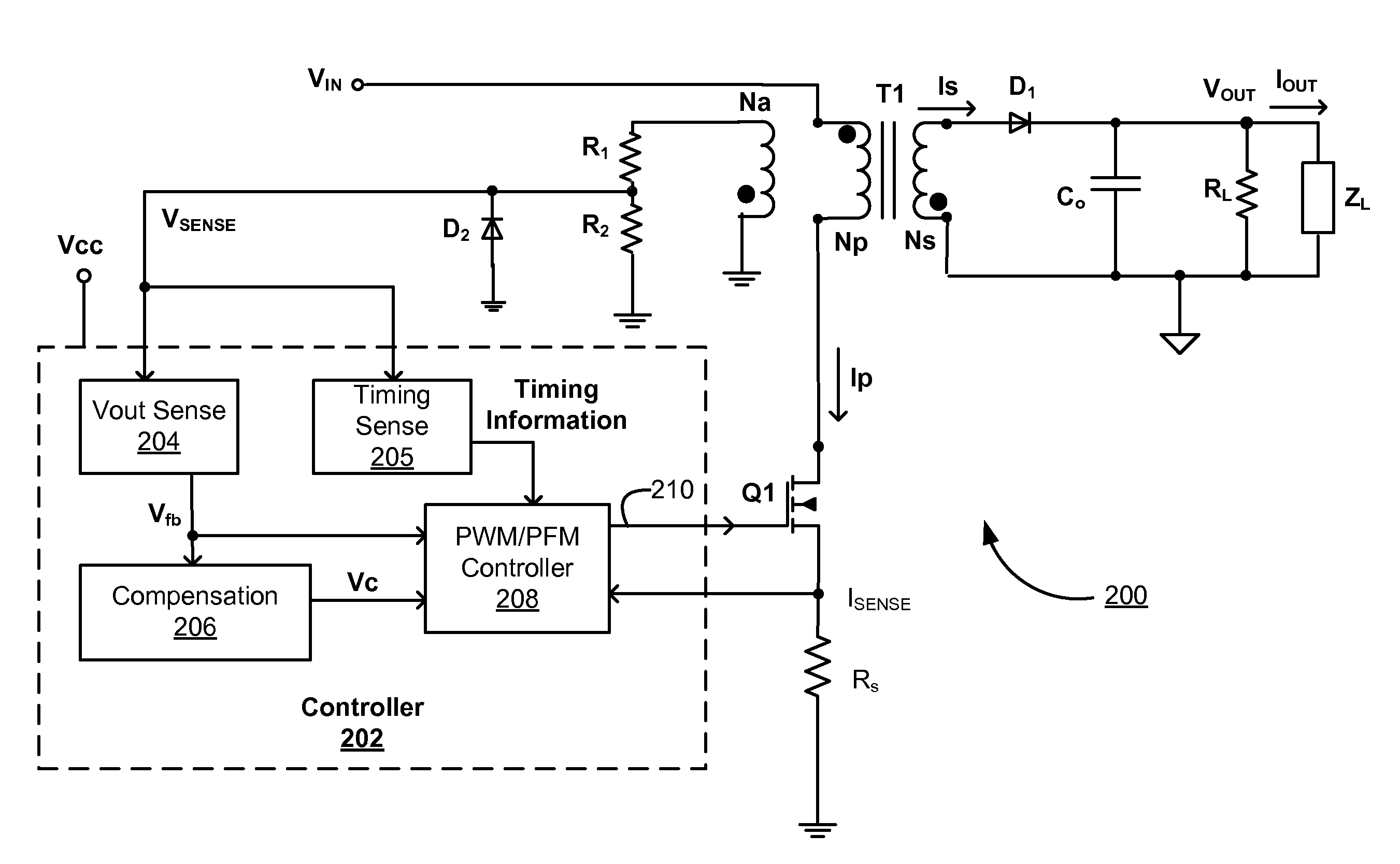
[0028]The Figures (FIG.) and the following description relate to preferred embodiments of the present invention by way of illustration only. It should be noted that from the following discussion, alternative embodiments of the structures and methods disclosed herein will be readily recognized as viable alternatives that may be employed without departing from the principles of the present invention.

[0029]Reference will now be made in detail to several embodiments of the present invention(s), examples of which are illustrated in the accompanying figures. It is noted that wherever practicable similar or like reference numbers may be used in the figures and may indicate similar or like functionality. The figures depict embodiments of the present invention for purposes of illustration only. One skilled in the art will readily recognize from the following description that alternative embodiments of the structures and methods illustrated herein may be employed without departing from the pr...


PUM


Abstract

In a switching power converter, PWM mode and PFM mode are separated into two independent control sections with the control voltage range in each control section determined independently. Each of the PWM and PFM modulation modes cannot operate continuously beyond its boundaries, thereby forming a control gap between the two control sections within which no continuous operation is allowed. In order to supply a load condition within the control gap, the power supply operates at the two boundaries of the control gap. Transition between PWM and PFM modes occurs fast, with low output voltage ripple. No limitation needs to be imposed on the control voltage range in each of the PWM and PFM control sections, because the control parameters in the PWM and PFM control sections need not be matched to one another, due to separation of the PWM and PFM modes by the control gap.

Description

CROSS REFERENCE TO RELATED APPLICATIONS[0001]This application is a continuation application of, and claims priority under 35 U.S.C. §120 from, U.S. patent application Ser. No. 12 / 398,878, filed on Mar. 5, 2009, which is incorporated by reference herein in its entirety.BACKGROUND OF THE INVENTION[0002]1. Field of the Invention[0003]The present invention relates to transitioning between different modulation modes in switching power converters (also referred to as switched mode power supplies) to reduce output voltage ripple and overshoot and undershoot during such transition.[0004]2. Description of the Related Arts[0005]In switched mode power supplies, power loss results from either current conduction loss or switching loss in the power switch. Under heavy load conditions, current is high and thus conduction loss is the dominating factor. However, under light load conditions, current is low and thus switching loss is the dominating factor.[0006]To improve the light load efficiencies o...

Claims


Application Information

Patent Timeline
Patent Type & Authority Applications(United States)
IPC IPC(8): H02M3/335
CPCH02M3/33507Y02B70/16H02M2001/0032Y02B70/10H02M1/0032G05F1/00G05F1/565
Inventor WANG, XIAOYANYAN, LIANGZHENG, JUNJIEKESTERSON, JOHN WILLIAMPOON, CLARITA
Owner DIALOG SEMICONDUCTOR INC
Learn More