Route setup server, route setup method and route setup program
a technology of route setup and program, which is applied in the direction of electrical equipment, data switching networks, digital transmission, etc., can solve the problems of increasing the number of route setup servers and the time required for route setup
- Summary
- Abstract
- Description
- Claims
- Application Information
AI Technical Summary
Benefits of technology
Problems solved by technology
Method used
Image
Examples
first exemplary embodiment
1. First Exemplary Embodiment
1-1. Configuration
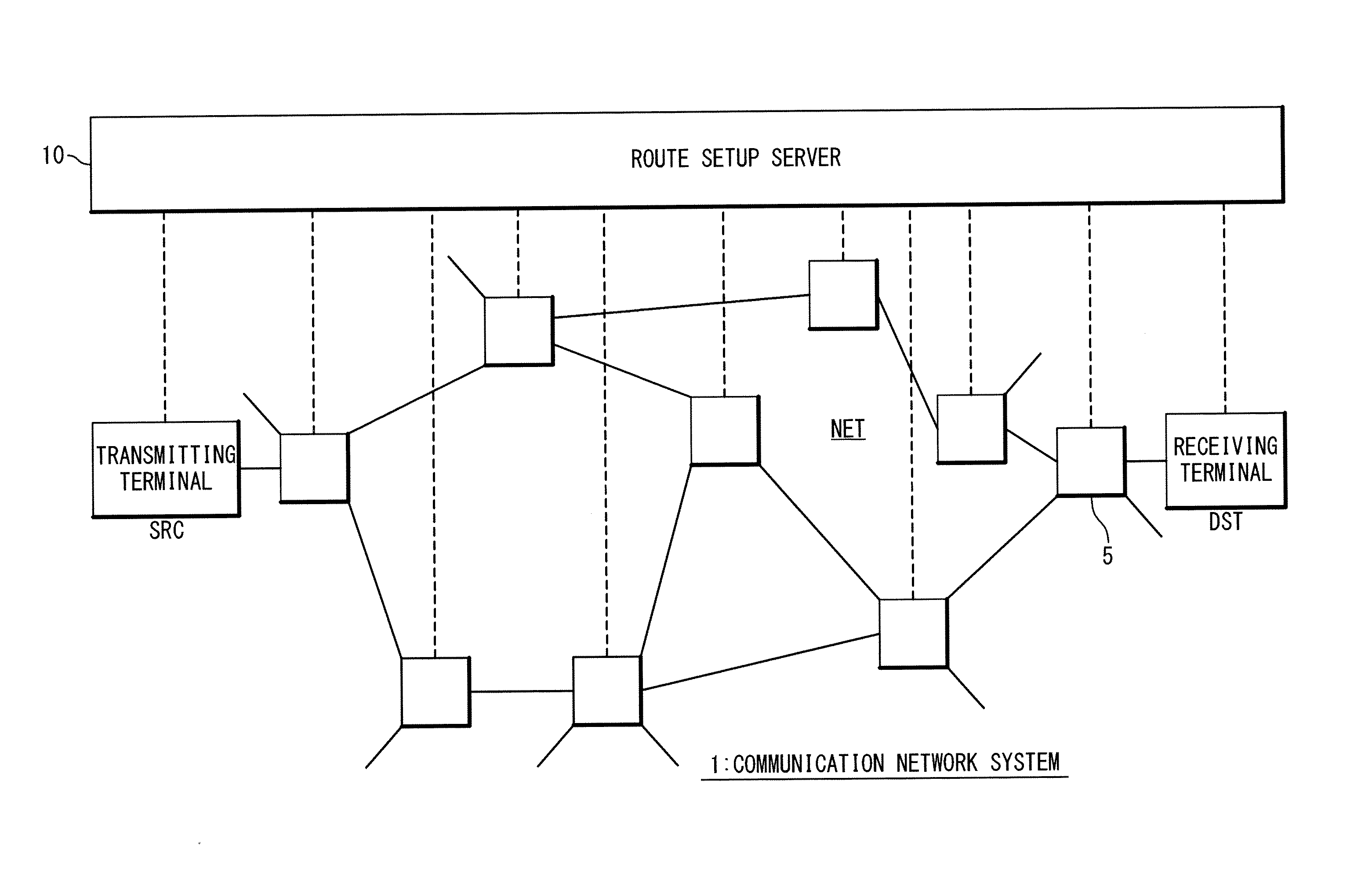
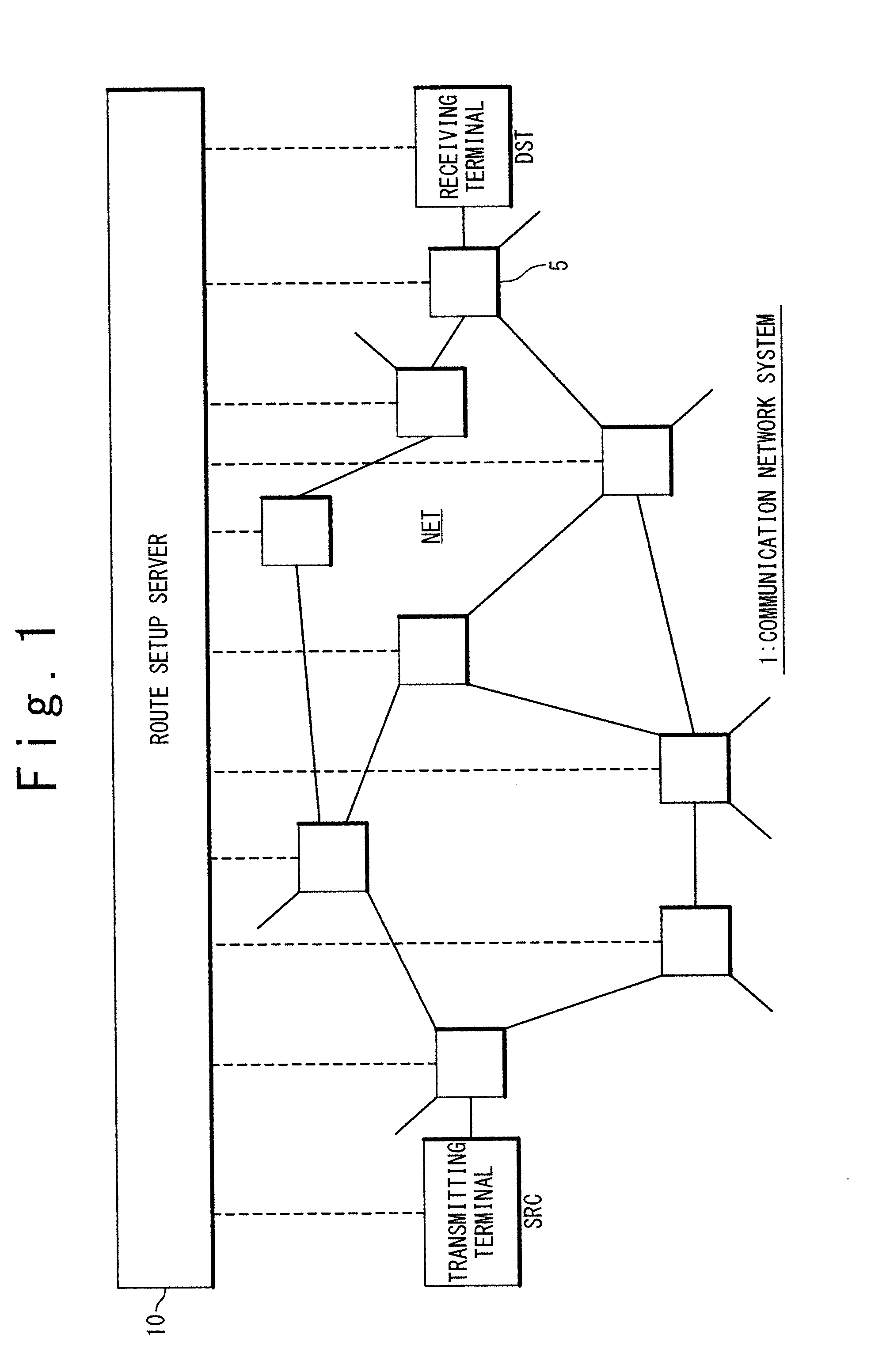
[0045]FIG. 3 is a block diagram showing a configuration of the route setup server 10 according to a first exemplary embodiment. The route setup server 10 has a flow management unit 100, an IP routing unit 200 and a storage unit 300.
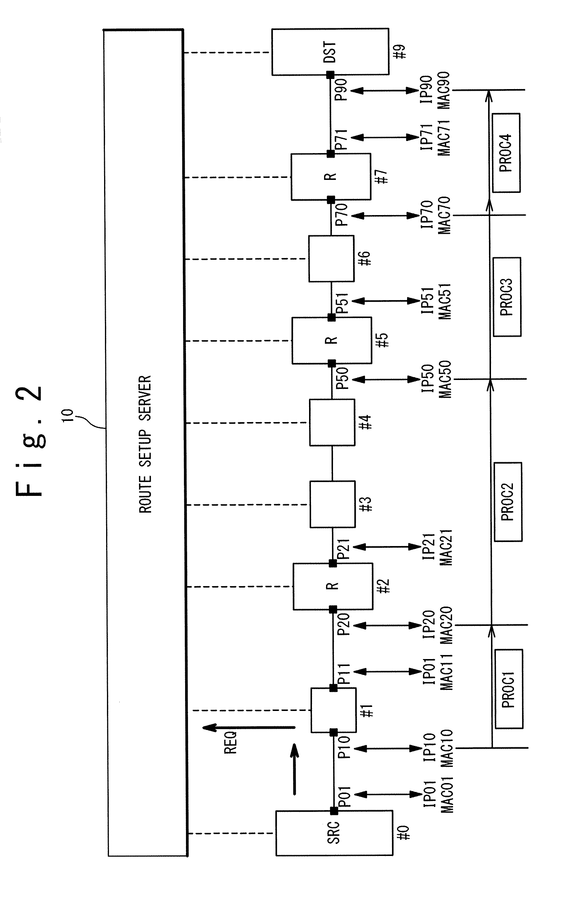
[0046]The flow management unit 100 receives the route setup request REQ and determines a communication route of the flow in response to the route setup request REQ. The flow management unit 100 is achieved by the route setup server 10 executing the route setup program. As shown in FIG. 3, the flow management unit 100 has a packet information acquisition unit 110, a routing determination unit 120, an end-point acquisition unit 130, a route designing unit 140, a node setting unit 150 and an end determination unit 160 as functional blocks. Processing by each functional block will be described later.
[0047]The IP routing unit 200 performs IP routing in a software manner. More specifically, the IP routing unit 200 ...
second exemplary embodiment
2. Second Exemplary Embodiment
[0091]In the above-described first exemplary embodiment, the route determination (Step S140) and the node setting (Step S150) are performed every time the routing processing is performed. According to a second exemplary embodiment, the route determination (Step S140) and the node setting (Step S150) are performed in a lump after the routing processing is repeated until the predetermined end condition is satisfied.
[0092]FIG. 8 is a flow chart showing the route setup processing according to the second exemplary embodiment. According to the present exemplary embodiment, the end determination (Step S160) by the end determination unit 160 is performed following the Step S130. The repetition of the routing processing is performed as in the case of the first exemplary embodiment.
[0093]If the predetermined end condition is satisfied (Step S160; Yes), the processing proceeds to Step S140. At Step S140, the route designing unit 140 determines in a lump a communic...
third exemplary embodiment
3. Third Exemplary Embodiment
[0095]In a third exemplary embodiment, a plurality of virtual networks are constructed on the communication network NET. The subnet configuration and the router node are different between the virtual networks. Therefore, the routing determination table 320 is prepared separately with respect to each virtual network.
[0096]FIG. 9 shows a configuration of the route setup server 10 according to the third exemplary embodiment. As shown in FIG. 9, the routing determination tables 320-1, 320-2 . . . for the respective virtual networks are stored in the storage unit 300. When referring to the routing determination table 320, the flow management unit 100 identifies a virtual network to which a packet belongs, based on such information as the header of the packet and transit nodes. Then, the flow management unit 100 refers to the IP routing table 320 associated with the identified virtual network. The others are the same as in the case of the foregoing exemplary e...
PUM
 Abstract
Description
Claims
Application Information
 - R&D
- Intellectual Property
- Life Sciences
- Materials
- Tech Scout
- Unparalleled Data Quality
- Higher Quality Content
- 60% Fewer Hallucinations
Browse by: Latest US Patents, China's latest patents, Technical Efficacy Thesaurus, Application Domain, Technology Topic, Popular Technical Reports.
© 2025 PatSnap. All rights reserved.Legal|Privacy policy|Modern Slavery Act Transparency Statement|Sitemap|About US| Contact US: help@patsnap.com


