
Helmet

Inactive Publication Date: 2011-12-01
TECASIA
View PDF7 Cites 27 Cited by
  • Summary
  • Abstract
  • Description
  • Claims
  • Application Information

AI Technical Summary

Benefits of technology

[0012]The helmet according to the invention only switches on the light source when the helmet is arranged on the head of the wearer. This is detected by the sensor. The sensor delivers a corresponding signal. The control device aligns the signal depending on whether the sensor has detected the arrangement of the helmet on a head and only if this is the case does the control device switch on the electric light source. Thus, the helmet ensures that the illumination device is only switched on when the helmet is on the head of the wearer. When the helmet is removed, the illumination device is switched off. Unnecessary power consumption is hereby avoided so that the illumination device can be used more frequently when visibility conditions require it. The helmet is thus safer than conventional helmets. The invention includes embodiments in which the illumination device is always switched on when the helmet is on the head of the wearer. But it also includes embodiments in which the electric control device only enables the switching on of the electric light source when the helmet is placed on the head. An additional switch is then required to switch on the light source; in particular, this can be a switch actuatable by hand or a dimmer switch. In the case of this embodiment, a switching on of the light source and thus the associated power consumption is avoided when the helmet is taken off.
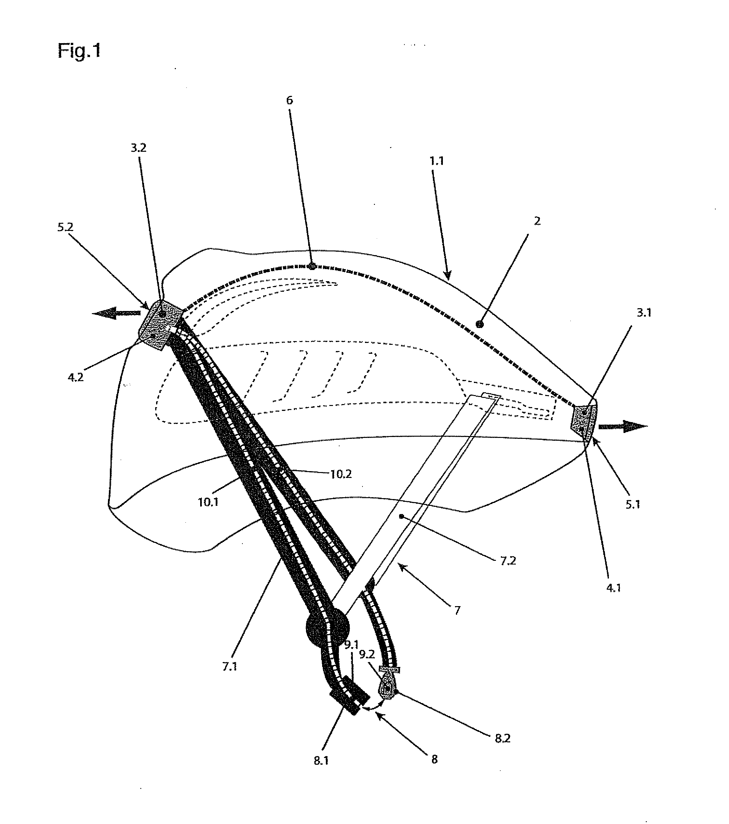
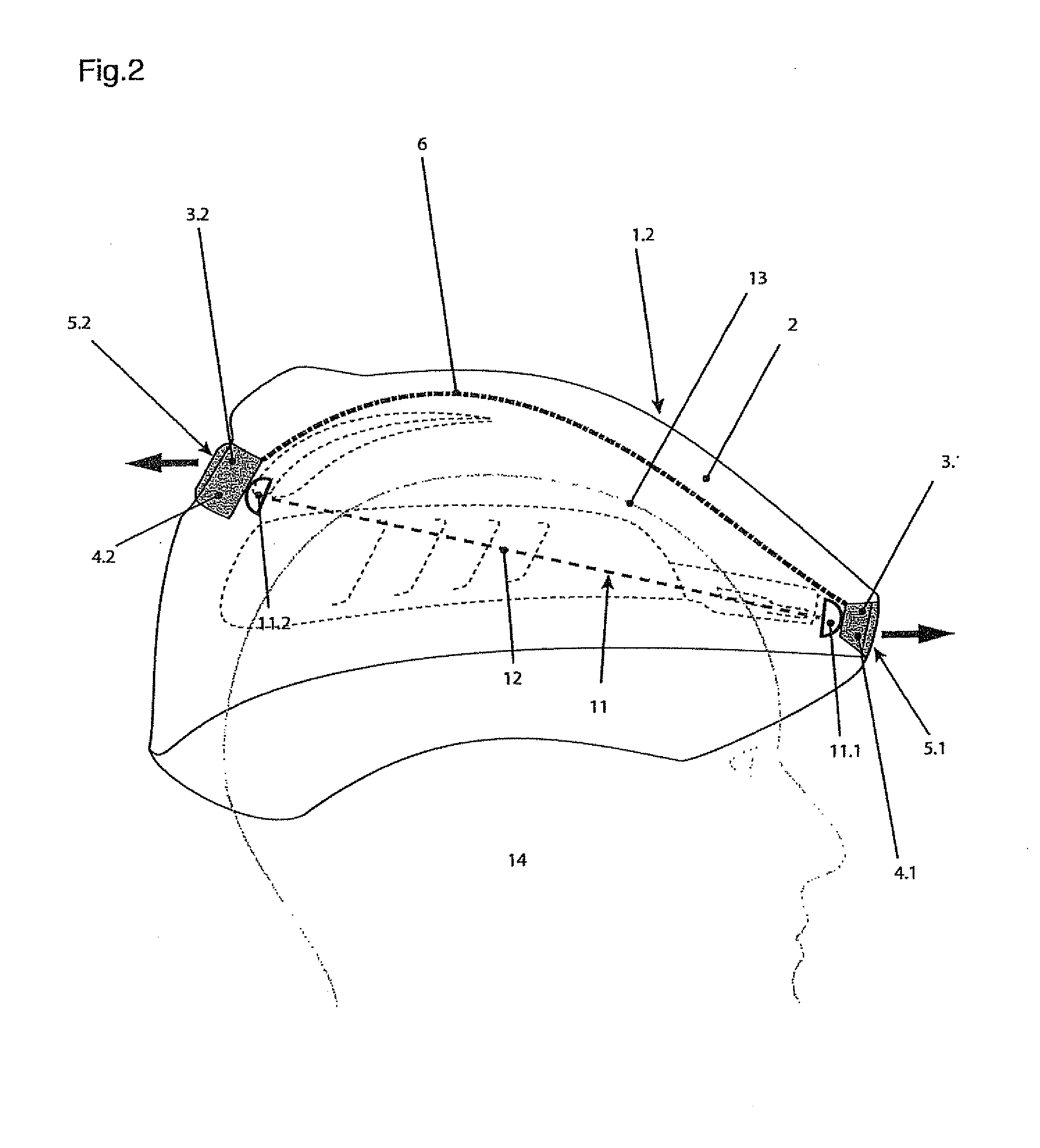
[0051]In the case of helmets according to the invention, the two bezels are displaced through displacement of the guide pin in another guide slot so that the other ventilation slots of the bezels more or less overlap the ventilation slots of the helmet shell. Thus, the cross-section of the ventilation slots on the helmet is adjustable and thus the quantity of the air let through the ventilation slots. In the case of low ambient temperatures, the ventilation slots can be completely or almost completely closed and can be completely or almost completely opened in the case of high ambient temperatures. In the case of medium temperatures, the ventilation slots and the other ventilation slots can be brought to overlap by approximately half. As a result, the helmet enables an adjustment for the respective ambient conditions. The wearing of the helmet is thus more comfortable than with conventional helmets, in which the ventilation slots are not changeable. As a result, a user uses the helmet for frequently and the helmet increases the safety of the wearer.

Problems solved by technology

This arrangement is placed outside over the crown area of the helmet, wherein the battery box on the back of the head area of the helmet is very bulky.
Despite the plurality of LEDs, the visibility of the strip arranged above the crown of the wearer is not particularly good.
However, the device is voluminous and, accordingly, the accommodation on a helmet is problematic, especially if it needs to be small and light for use during sports.
It is also disadvantageous that the known illumination devices must be switched on and off so that they are not always switched on in poor visibility conditions or remain switched on during sufficient visibility conditions and use power unnecessarily.
Furthermore, known helmets are disadvantageous in that cold air can get into the helmet shell on the head of the often sweaty wearer through ventilation slots in the helmet shell during cold weather so that the wearer runs the risk of getting a cold.

Method used


Image

  • Helmet
  • Helmet
  • Helmet

Examples


Embodiment Construction

[0068]While this invention may be embodied in many different forms, there are described in detail herein a specific preferred embodiment of the invention. This description is an exemplification of the principles of the invention and is not intended to limit the invention to the particular embodiment illustrated

[0069]In the case of the following explanation of different exemplary embodiments, corresponding parts are provided with the same reference numbers. The words “top,”“bottom,”“front” and “back” as well as “horizontal” and “vertical” refer to a helmet, which is worn by a person in an upright body position gazing forward towards the horizon.

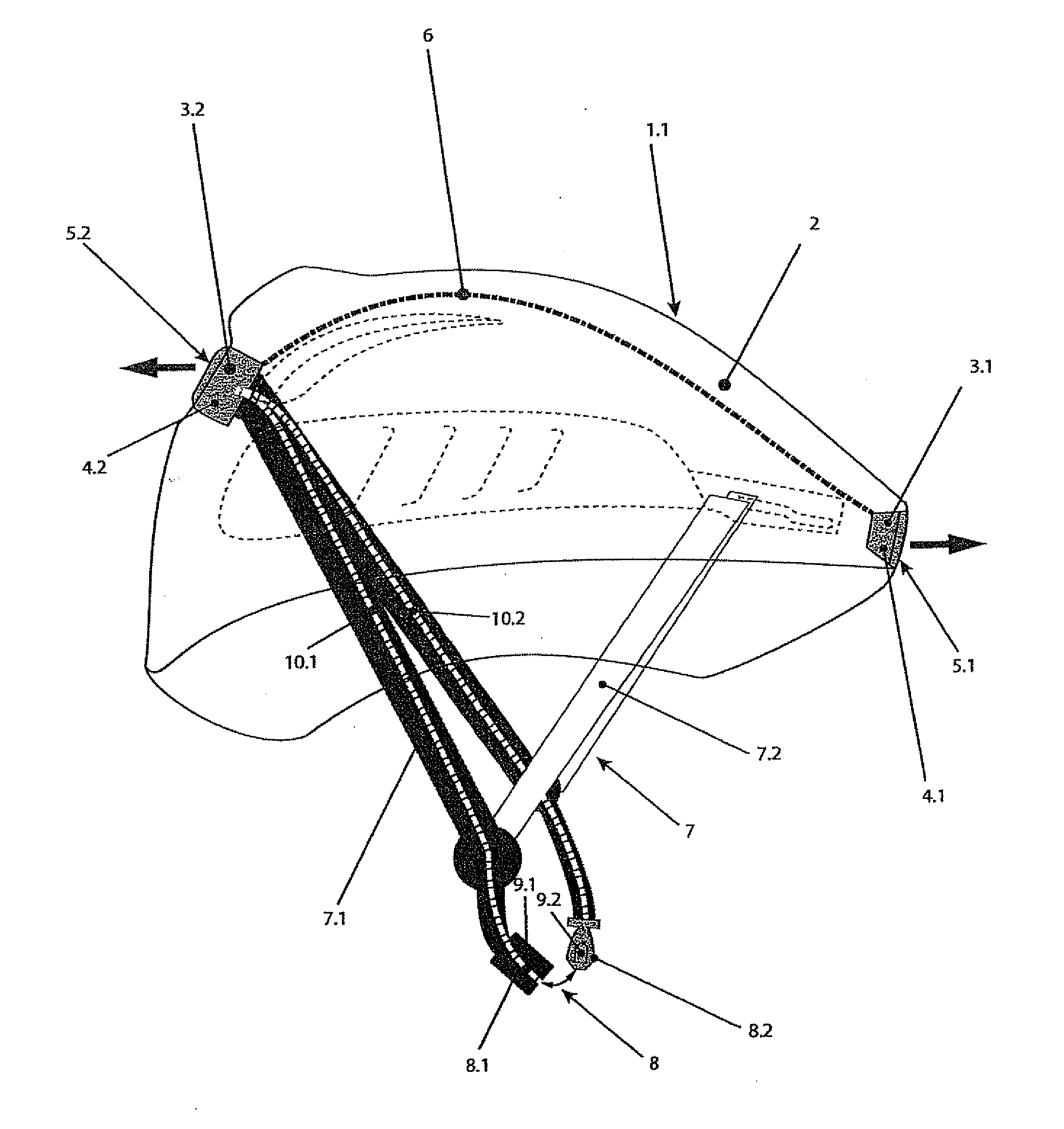
[0070]According to FIG. 1, a helmet 11 has a helmet shell 2. An illumination device 3, which comprises a front light 3.1 on the front edge of the helmet shell 2, which is arranged above the forehead, is inserted into the helmet shell 2.

[0071]Furthermore, the illumination device 3 comprises a rear light 3.2, which is arranged on the back of the...


PUM


Abstract

A helmet with an illumination device with at least one electric light source arranged on the outside of the helmet shell, a sensor for detecting the arrangement of the helmet on a head, an electric control device and an electric voltage source electrically connected with the electric light source and the sensor, wherein the electric control device is designed such that it switches on the electric light source or only permits the switching on of the electric light source when the sensor detects the arrangement of the helmet on a head.

Description

CROSS-REFERENCE TO RELATED APPLICATIONS[0001]Not applicable.STATEMENT REGARDING FEDERALLY SPONSORED RESEARCH[0002]Not applicable.BACKGROUND OF THE INVENTION[0003]The invention relates to a helmet, which can be designed in particular as a helmet for bicyclists and / or skiers. However, the helmet can also be designed for skaters, skateboarders, snowboarders or other athletes.[0004]Helmets with an illumination device serve for better detection of bicyclists at night or respectively in bad visibility and, if applicable, when the road is poorly lit.[0005]U.S. Pat. No. 5,544,027 discloses an LED device, which can be attached to conventional or new bicycle helmets, in order to improve detectability in evening hours. LEDs are connected via an electric line with an electric voltage source such as a battery arranged in the helmet, or with an external voltage source, such as with a dynamo arranged on a bicycle. In one exemplary embodiment, a plurality of LEDs is arranged in series behind each o...

Claims


Application Information

Patent Timeline
IPC IPC(8): H05B37/02A42B3/28F21L4/08
CPCA42B3/0433A42B3/044F21Y2101/02F21V23/0442F21V33/0064F21L4/00F21Y2115/10
Inventor KNOEPFLI, MARTINGMUER, JONAS
Owner TECASIA
Learn More