Method and Apparatus for Maintaining Pressure In Well Cementing During Curing

a well and cementing technology, applied in the direction of fluid removal, sealing/packing, borehole/well accessories, etc., can solve the problems of lack of zonal isolation, lack of life and property, and the casing shoes may not test at expected pressure integrity, etc., to increase the radial stress of cured cement and increase the hydrostatic pressure

Inactive Publication Date: 2011-12-01
COOKE JR CLAUDE E
View PDF4 Cites 18 Cited by
  • Summary
  • Abstract
  • Description
  • Claims
  • Application Information

AI Technical Summary

Benefits of technology

[0016]Apparatus and method are provided for pumping down and mechanically coupling to the casing a source or sources of impulses or vibrations that are activated by pressure changes in the casing and then retrieved or drilled or milled from the casing or moved to a segment of the casing that is not to be used in further well operations. Power for the source of the impulses may be supplied by fluid pressure changes in the casing resulting from alternately pumping in and releasing fluid from the casing. Sources for the impulse or vibration may be pumped to the locations along the casing string by launching them into the displacing fluid while cement is being displaced from the casing or dropping them after the plug has been bumped. The devices for applying impulses to the casing may be locked in place (mechanically coupled) in sections of the casing adapted for receiving the devices or may be locked by a locking mechanism in the device. In one embodiment, the source of an impulse may be a mechanical or hydraulic jar, such as that known in the industry. The jars may be activated by an increase in hydrostatic pressure in the casing. Potential energy stored in the jar may be derived from a pressure increase in the casing. Other sources of energy, such as chemical reactions may be used to induce the impulses or vibrations in the casing. Alternately, the devices may be vibrators driven by flow of fluid under pressure that is created by increase and decrease in pressure in the casing or from other sources. The devices in the casing are operated as the cement cures to maintain pressure in the cement above pore pressure in zones in contact with the cement for a selected time and to increase the radial stress in cured cement. After cement curing, the devices may be recovered to the surface, where they may be re-used, or they may be expendable devices that are removed by drilling or milling from the casing (casing above production casing) or they may be moved to a segment of the casing where they are not interfering with further operations in the well, such as a rathole (production casing).

Problems solved by technology

The resulting loss of control of a well has been responsible for loss of life and property for many years.
In addition to the well control issue, annular fluid flow of fluids between zones before the cement cures can cause lack of zonal isolation in wells; water flow to surface from shallow pressurized water sands may occur; and casing shoes may not test at expected pressure integrity.
The limitation of this method is that the amplitude of any vibrations caused outside the casing would be very small and of very limited extent along the axis of the casing.
The limitation to this method is that it would be necessary to run a pipe in the casing after cement is pumped, which would be expensive and time-consuming, and it would be difficult to apply a jarring force in more than one location along the casing.
There are at least two disadvantages to the use of vibration sources on a wireline or a pipe string: (1) the wireline or string cannot enter a casing until after cement is pumped, and then delivering the vibration sources to a plurality of preferred depths in the casing would be time-consuming and expensive; (2) the power available for a vibrator would be severely limited by the power transmission capabilities of a wireline.
Similar limitations exist for use of explosive charges to propel a projectile against the casing wall.
As the cement cures, gel strength increases, which means that breaking gel strength in the cement column, such that the cement will flow, will become more difficult as time-after-pumping increases.
No evidence is presented, however, that vibration only near the bottom of a casing string will allow the pressure in cement to increase near the bottom of the casing.
Cement slurry being pumped down a casing flows through a device, powering the device and causing vibrations in the casing.
All prior art methods disclosed for inducing vibration into a casing to prevent pressure drop in the cement column have been limited by applying vibration only at the top end or the bottom end of the casing or, if vibration is induced at intermediate points along the casing, by placing apparatus in the casing after pumping of cement has ended (the top plug has been “bumped”).

Method used


Image

  • Method and Apparatus for Maintaining Pressure In Well Cementing During Curing
  • Method and Apparatus for Maintaining Pressure In Well Cementing During Curing
  • Method and Apparatus for Maintaining Pressure In Well Cementing During Curing

Examples


Embodiment Construction

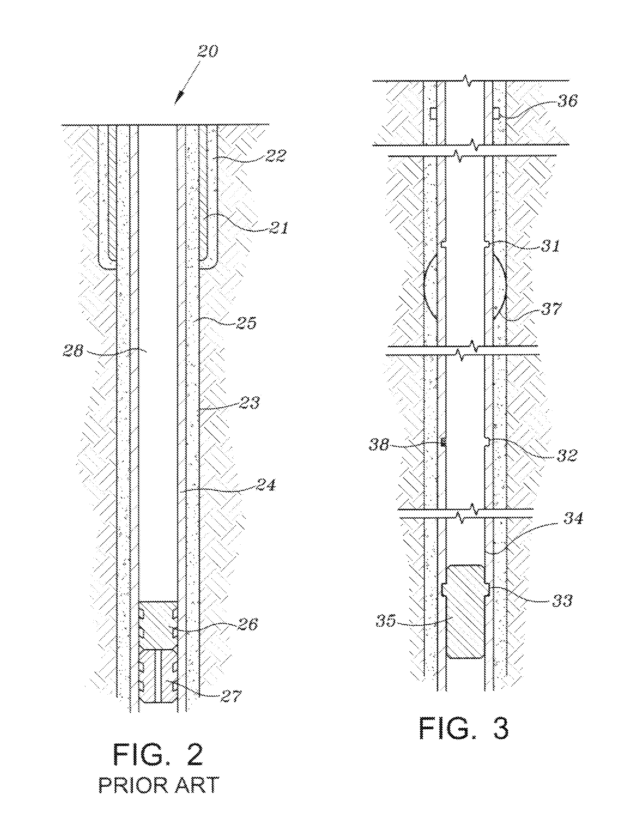
[0027]Referring to FIG. 2 (prior art), well 20 has been drilled by first drilling a hole and cementing casing 21 (conductor casing) with cement 22. A second smaller diameter hole 23 has been drilled out of the bottom of the conductor casing and casing string 24 (“surface casing”) has been cemented in place using cement 25. The cementing operation is well known in the industry. It may involve launching a bottom plug 27 ahead of the cement, pumping the cement, breaking a diaphragm in the bottom plug and launching top plug 26 behind the cement and displacing it with displacement fluid 28 (normally brine or drilling fluid). Sufficient cement may be placed in the well to bring the top of cement back to the surface of the earth (as shown) or the top of the cement may be brought to some selected depth below the surface of the earth. The surface casing extends to a depth below the surface of the earth sufficient to protect all usable water zones. It is very important that the surface casing...


PUM

PropertyMeasurementUnit
pore pressureaaaaaaaaaa
flow rateaaaaaaaaaa
frequencyaaaaaaaaaa

Abstract

Method and apparatus are provided for cementing wells and preventing fluid entry into the wellbore before the cement cures and increasing radial stress in the cured cement. Impacts or vibrations are applied to the casing during the time that the cement is curing. The source or sources of the impacts or vibration are placed in the casing during displacement of the cement slurry or soon after placement and are mechanically coupled to the inside wall of the casing. The sources may later be withdrawn from the casing or expendable sources may be used.

Description

[0001]This application claims priority to provisional application Ser. No. 61 / 349,092 filed on May 27, 2010 and provisional application Ser. No. 61 / 412,671 filed on Nov. 11, 2010. These applications are hereby incorporated by reference in their entirety.BACKGROUND OF INVENTION[0002]1. Field of the Invention[0003]This invention relates to cementing of casings in wells. More particularly, method and apparatus are provided for preventing entry of fluids from the surrounding rock into the cement before it cures and for attaining higher radial stress in the cured cement.[0004]2. Background of the Invention[0005]The phenomenon of annular fluid flow (called “annular gas flow” when gas comes to the surface) has long been known to occur during cementing of wells. It is caused by fluids from the surrounding rock entering the wellbore before the cement cures. The resulting loss of control of a well has been responsible for loss of life and property for many years. In addition to the well contr...

Claims


Application Information

Patent Timeline
Patent Type & Authority Applications(United States)
IPC IPC(8): E21B33/13E21B43/00
CPCE21B23/02E21B33/14E21B33/05E21B28/00
Inventor COOKE, JR., CLAUDE E.
Owner COOKE JR CLAUDE E
Why Eureka
Try Eureka