Ambient light sensing module

Active Publication Date: 2011-12-01
SENSORTEK TECH
View PDF9 Cites 22 Cited by
  • Summary
  • Abstract
  • Description
  • Claims
  • Application Information

AI Technical Summary

Benefits of technology

Another objective of the present invention is to provide an ambient light sensing module, which has at least a fuse for determining the processing parameters of the ambient light sensing module. The processing parameters can be modified by trimming the fuse via a trimming unit for adjusting the characteristics of the ambient light sensing module. Hence, the accuracy of the ambient light sensing module can be improved.

Problems solved by technology

Nonetheless, the light-sensing signal output by a modern ambient light sensor cannot be used directly for controlling the back-stage circuit of the electronic device.
Consequently, the burden and cost of the electronic device are increased.
Even the characteristics of ambient light sensors manufactured using identical materials and processes may not be completely identical.
Thereby, while sensing the same light source using different ambient light sensors, the light-sensing signals output by these ambient light sensors differ, which causes an electronic device unable to know the light intensity of the light source with accuracy and hence unable to execute the corresponding functions accurately.
Even worse, erroneous functions might be executed instead.
Based on the above description, it is known that modem electronic devices are influenced by the not-completely-identical characteristics of their ambient light sensors, which may lead to deterioration of their performance.

Method used


Image

  • Ambient light sensing module
  • Ambient light sensing module
  • Ambient light sensing module

Examples


Embodiment Construction

in order to make the structure and characteristics as well as the effectiveness of the present invention to he further understood and recognized, the detailed description of the present invention is provided as follows along with embodiments and accompanying figures.

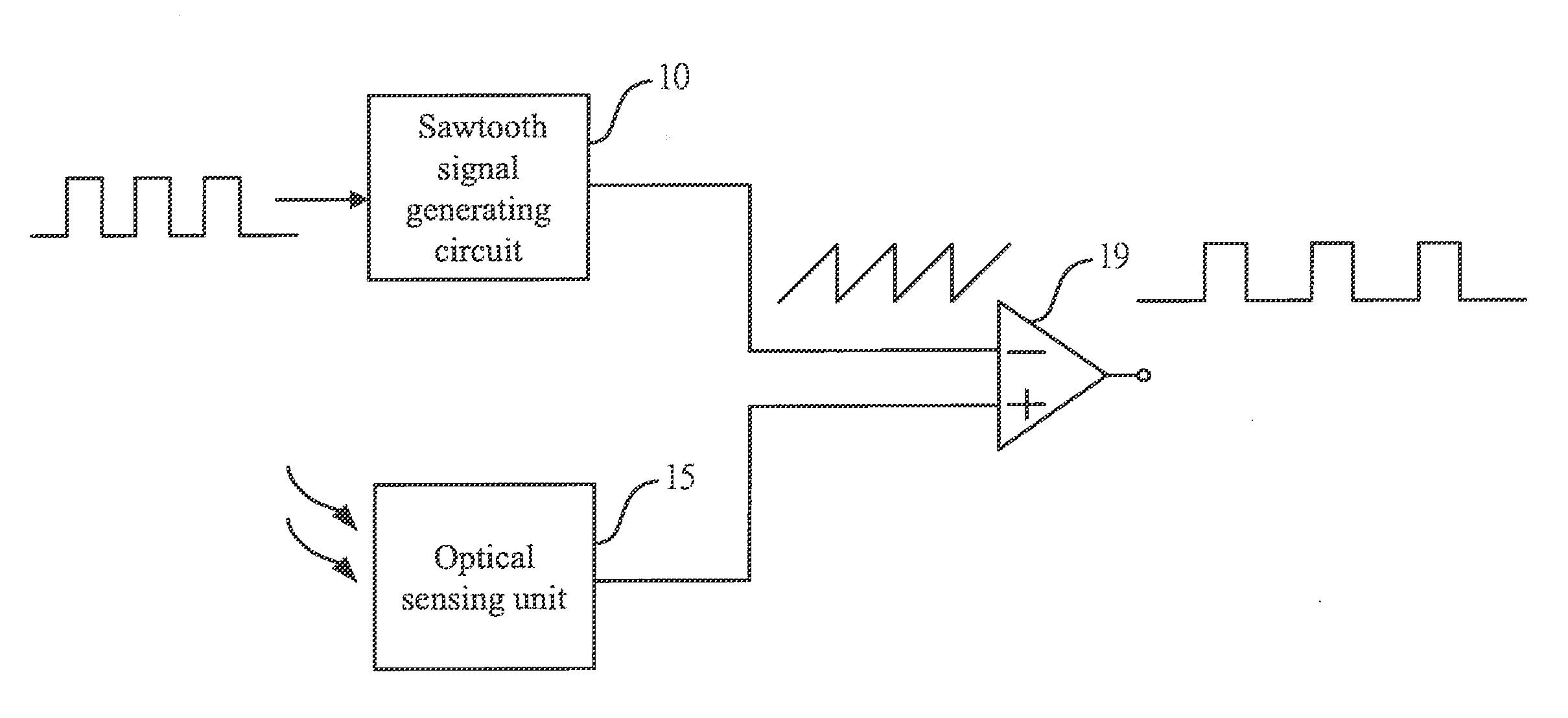
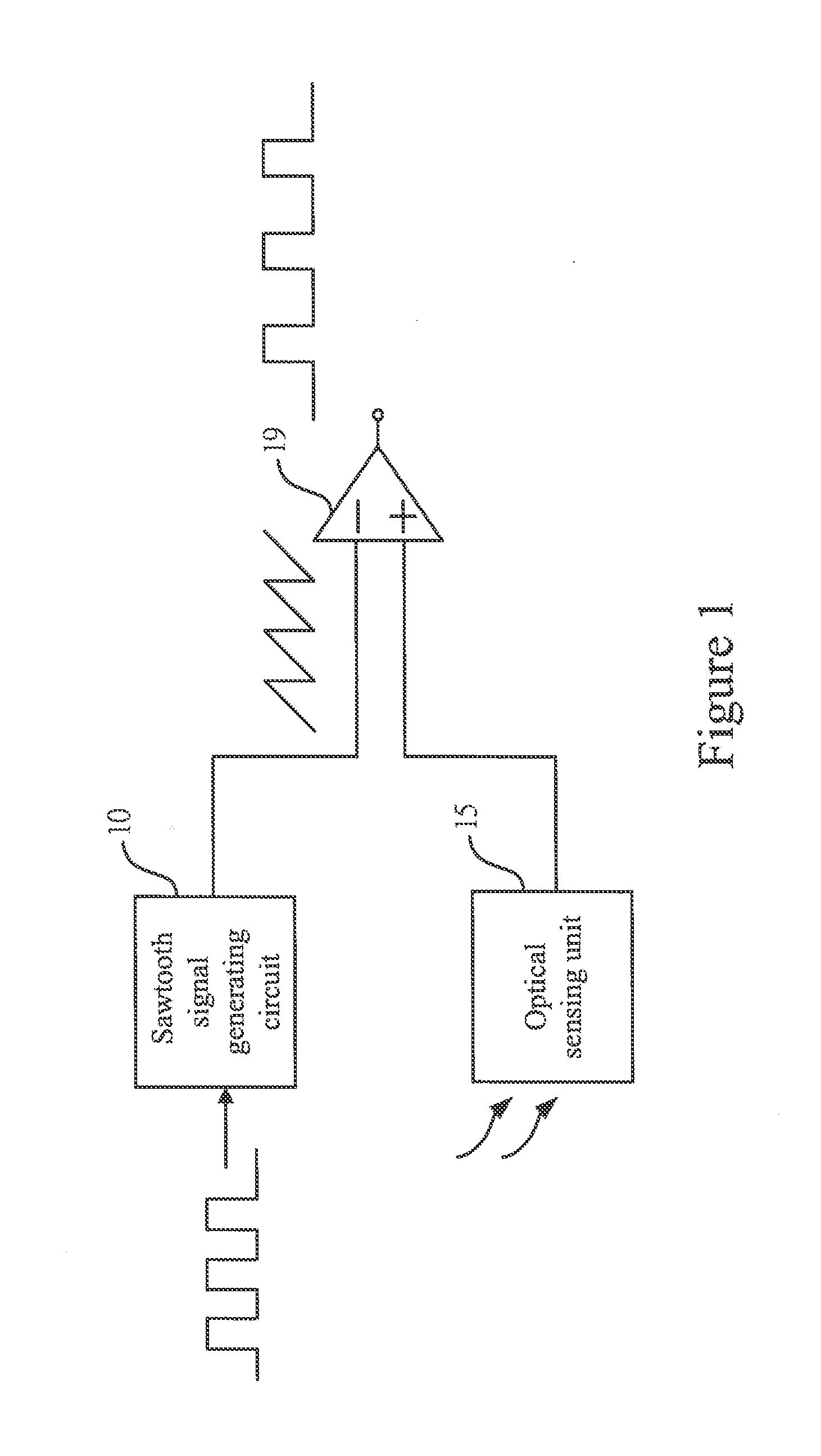
FIG. 1 shows a block diagram of an ambient light sensing module according to an embodiment of the present invention. As shown in the figure, the ambient light sensing module according to the present invention comprises a sawtooth signal generating circuit 10, an optical sensing unit 15, and a comparing unit 19. The optical sensing unit 15 is used for sensing the light intensity and producing a corresponding light-sensing signal. The characteristics of the light-sensing signal are related to the light intensity. For example, when the light intensity is high, the amplitude of the light-sensing signal is large. On the contrary, when the light intensity is weak, the amplitude of the light-sensing signal is low. The sawtooth ...


PUM


Abstract

The present invention provides an ambient light sensing module, which comprises a sawtooth signal generating circuit, an optical sensing unit, and a comparing unit. The sawtooth signal generating circuit produces a sawtooth signal. The optical sensing unit senses a light source and produces a light-sensing signal. The comparing unit produces a pulse-width modulation (PWM) signal related to the intensity of the light source according to the light-sensing signal and the sawtooth signal so that the PWM signal can be used as the control signal of the electronic device. The ambient light sensing module further comprises at least a fuse for determining a processing parameter. A signal processing unit processes the light-sensing signal according to the processing parameter for outputting a converting signal. The comparing unit compares the converting signal with the sawtooth signal for producing the PWM signal. An adjusting unit produces an adjusting signal according to the PWM signal and the light intensity or according to the converting signal and the light intensity for controlling a trimming unit to trim the fuse and thus modifying the processing parameter.

Description

FIELD OF THE INVENTIONThe present invention relates generally to a sensing module, and particularly to an ambient light sensing module for sensing the light intensity.BACKGROUND OF THE INVENTIONPresently, thanks to progress in technologies, many electronic devices are developed for satisfying people's demands. For providing people with more convenience in lives, electronic devices with increasingly stronger functionality are introduced. In order to enhance functions of electronic devices, ambient light sensors are disposed for sensing the light intensity in the environment and hence executing the corresponding functions such as adjusting the light intensity of the backlight module of an electronic device or telling the user the light intensity in the environment. In addition, ambient light sensors can be disposed in cameras so that the flashlight can be activated automatically once the environmental light intensity is insufficient. Thereby, it is known from the above that the applic...

Claims


Application Information

Patent Timeline
IPC IPC(8): G01J1/46G01J1/44
CPCG01J1/46H03K4/50G01J1/4204H03M1/504H03K7/08
Inventor LIU, MING-HUANGLIN, MENG-YUNG
Owner SENSORTEK TECH
Why Eureka
Try Eureka