Piezoelectric devices including frequency-adjustment units

a frequency adjustment unit and piezoelectric technology, applied in piezoelectric/electrostrictive/magnetostrictive devices, piezoelectric/electrostriction/magnetostriction machines, electrical equipment, etc., can solve the problem of increasing the difficulty of removing only a desired amount of metal from the end of the arm, difficult access to the region, and difficulty in producing a controlled laser beam. problem, to achieve the effect of reducing manufacturing defects

Inactive Publication Date: 2011-12-01
NIHON DEMPA KOGYO CO LTD
View PDF1 Cites 9 Cited by
  • Summary
  • Abstract
  • Description
  • Claims
  • Application Information

AI Technical Summary

Benefits of technology

[0016]Thus, piezoelectric devices are provided of which the vibration frequency can be adjusted without having to change the dose of irradiation or the duration of the irradiation. This substantially reduces manufacturing defects.

Problems solved by technology

This increases the difficulty of removing only a desired amount of metal from the ends of the arms.
On the other hand, to reduce vibration frequency by a large amount, a large amount of source metal is required to supply a sufficient amount for deposition on the distal ends of the vibrating arms.
Usually, this supply of metal is located on the base plate near the bases of the vibrating arms, which is a difficult region to access using a laser beam.
Another complication is the difficulty of producing a controlled laser beam that the produces a desired amount and duration of irradiation required for accurately and precisely producing a specified adjustment of vibration frequency.
This substantially increases the difficulty of adjusting the amount of irradiation from the laser beam to achieve adjustments (especially small adjustments) of the vibration frequency produced by a tuning-fork type piezoelectric vibrating piece.

Method used


Image

  • Piezoelectric devices including frequency-adjustment units
  • Piezoelectric devices including frequency-adjustment units
  • Piezoelectric devices including frequency-adjustment units

Examples


first embodiment

of a Piezoelectric Device

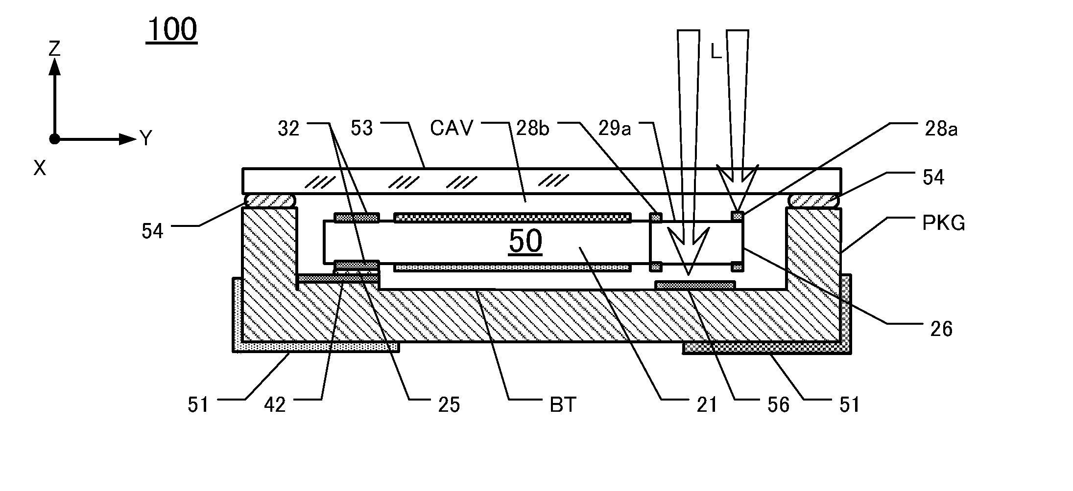
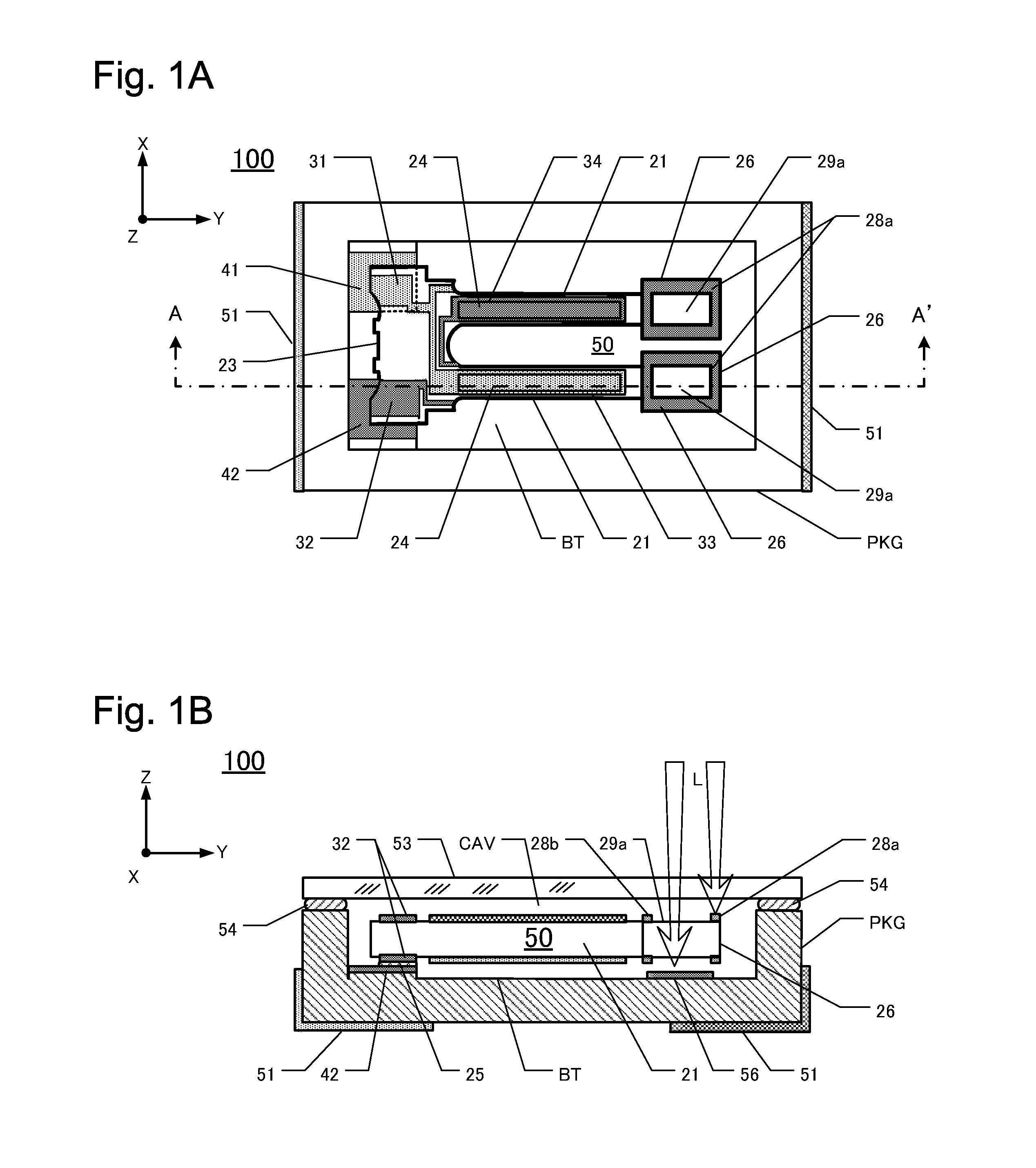
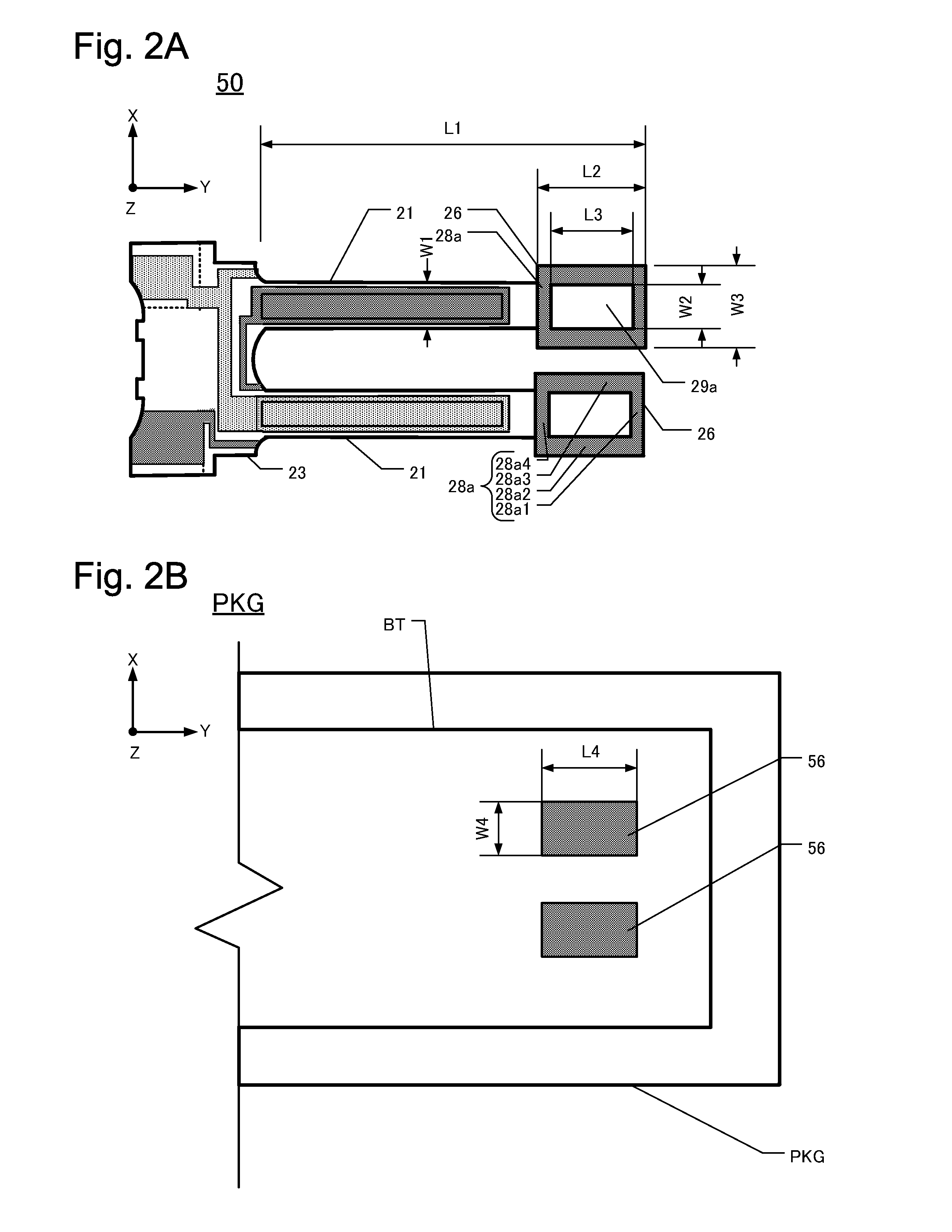
[0040]FIG. 1A is a plan view of this embodiment of a piezoelectric device 100 from which the lid 53 has been removed to reveal underlying detail. FIG. 1B is a cross-sectional view along the line A-A′ in FIG. 1A. The piezoelectric device 100 comprises a tuning-fork type crystal vibrating piece 50 contained within a package PKG. The crystal vibrating piece 50 comprises a base 23 and a pair of vibrating arms 21. The base 23 has a board shape and is fabricated of a crystalline material such as quartz crystal. The vibrating arms 21 extend parallel to each other in the y-axis direction from the base 23. With the exception of their distal ends, the vibrating arms 21 have a substantially constant width in the x-axis direction. On each of the upper and lower main surfaces of each vibrating arms 21 is a respective groove 24. One respective groove 24 is formed on each of the upper and lower main surfaces of one vibrating arm 21, and one respective groove 24 is formed o...

second embodiment

of Piezoelectric Vibrating Device

[0072]FIG. 5A is a plan view of this embodiment of a piezoelectric device 110 (with lid 53 removed) and FIG. 5B is a cross-section along the line B-B′ line of FIG. 5A. The principal difference between second piezoelectric devices 110 and 100 concerns the particular tuning-fork type crystal vibrating piece 60 used in the second embodiment compared to the first embodiment. Also, the second embodiment 110 has one large first metal film 57, instead of a pair of first metal films 56 as used in the first embodiment.

[0073]The piezoelectric device 110 is manufactured by placing the tuning-fork type crystal vibrating piece 60 inside a cavity CAV defined by a package PKG, followed by bonding a lid 53 to the package PKG using sealing material 54. Bonding of the lid to the package is performed in a vacuum. In this embodiment, components that are similar to corresponding components of the first embodiment had the same respective reference numerals and are not des...

third embodiment

of Piezoelectric Device

[0083]FIG. 7A is a plan view of this embodiment of a piezoelectric device 120, and FIG. 7B is a cross-section along the line C-C′ in FIG. 7A. The difference between this embodiment and the second embodiment is that, in the third embodiment 120, the tuning-fork type crystal vibrating piece 65 mounted in the package PKG has a pair of fan-shaped first metal films 58, instead of one large first metal film 57 as used in the second embodiment.

[0084]The third embodiment of a piezoelectric device 120 is fabricated by mounting the tuning-fork type crystal vibrating piece 65 inside a cavity CAV defined in a package PKG, and bonding a lid 53 to the package PKG in a vacuum using a sealing material 54. In the following description, components that are similar to corresponding components in the second embodiment have the same respective reference numerals and are not described further below.

[0085]As shown in FIG. 7A, each vibrating arm 21 includes a fan-shaped wide portion ...


PUM


Abstract

Piezoelectric devices are disclosed that allow outside-in adjustment of vibration frequency produced by the devices. I.e., the vibration frequency can be increased or reduced. An exemplary piezoelectric device includes a tuning-fork type piezoelectric vibrating piece mounted inside a package. The vibrating piece has a base fabricated of a piezoelectric material, a pair of vibrating arms extending parallel from the base in a predetermined direction, and a frequency-adjustment unit situated on the distal ends of the vibrating arms. The package includes first metal films disposed on the inner main surface of the package at a location where a beam from an external laser can be irradiated. The frequency adjustment unit includes a transparent region that extends in a predetermined direction for allowing the laser beam, passing through the lid of the package, to be incident on second metal films by passing through the transparent regions. The laser beam also can be incident on first metal films without also being incident on the second metal films, by passing through the lid but not through the transparent regions.

Description

CROSS-REFERENCE TO RELATED APPLICATION[0001]This application claims priority to and the benefit of Japan Patent Application No. 2010-122288, filed on May 28, 2010, in the Japan Patent Office, the disclosure of which is incorporated herein by reference in its entirety.FIELD[0002]This disclosure pertains to, inter alfa, piezoelectric devices that comprise a pair of vibrating arms and a means for adjusting their vibration frequency.DESCRIPTION OF THE RELATED ART[0003]In the general technology of fabricating piezoelectric vibrating devices of the tuning-fork type, the vibration frequency produced by the electrically excited vibration arms is usually adjusted by evaporating or ablating away portions of metal films formed on the distal ends of the vibrating arms using a laser beam. For example, Japan Unexamined Patent Application No. 2003-060470 discusses tuning-fork type piezoelectric vibrating pieces of which the vibrating arms initially have a lower vibration frequency than specified. ...

Claims


Application Information

Patent Timeline
Patent Type & Authority Applications(United States)
IPC IPC(8): H01L41/053
CPCH03H9/0595H03H9/1021H03H2003/0492H03H9/21H03H2003/0428H03H9/1035
Inventor KAWASE, YUICHIMOTEGI, TOSHIAKI
Owner NIHON DEMPA KOGYO CO LTD
Why Eureka
Try Eureka