Heating device

A technology for electric heating devices and heating elements, which is applied in the direction of electric heating devices, coupling devices, heating elements, etc., and can solve problems such as inconvenient connection, instability, and influence on brazing

Pending Publication Date: 2021-03-30
VALEO AUTOMOTIVE AIR CONDITIONING HUBEI CO LTD
View PDF0 Cites 0 Cited by
  • Summary
  • Abstract
  • Description
  • Claims
  • Application Information

AI Technical Summary

Problems solved by technology

During the soldering of the first bus bar terminal to the printed circuit board (PCB), this unstable force causes the first bus bar terminal to lose contact with t...

Method used


Image

  • Heating device
  • Heating device
  • Heating device

Examples


Embodiment Construction

[0034] It should be noted that the accompanying drawings disclose the invention in sufficient detail, if necessary, to help better define the invention. However, the present invention should not be limited to the embodiments disclosed in the specification.

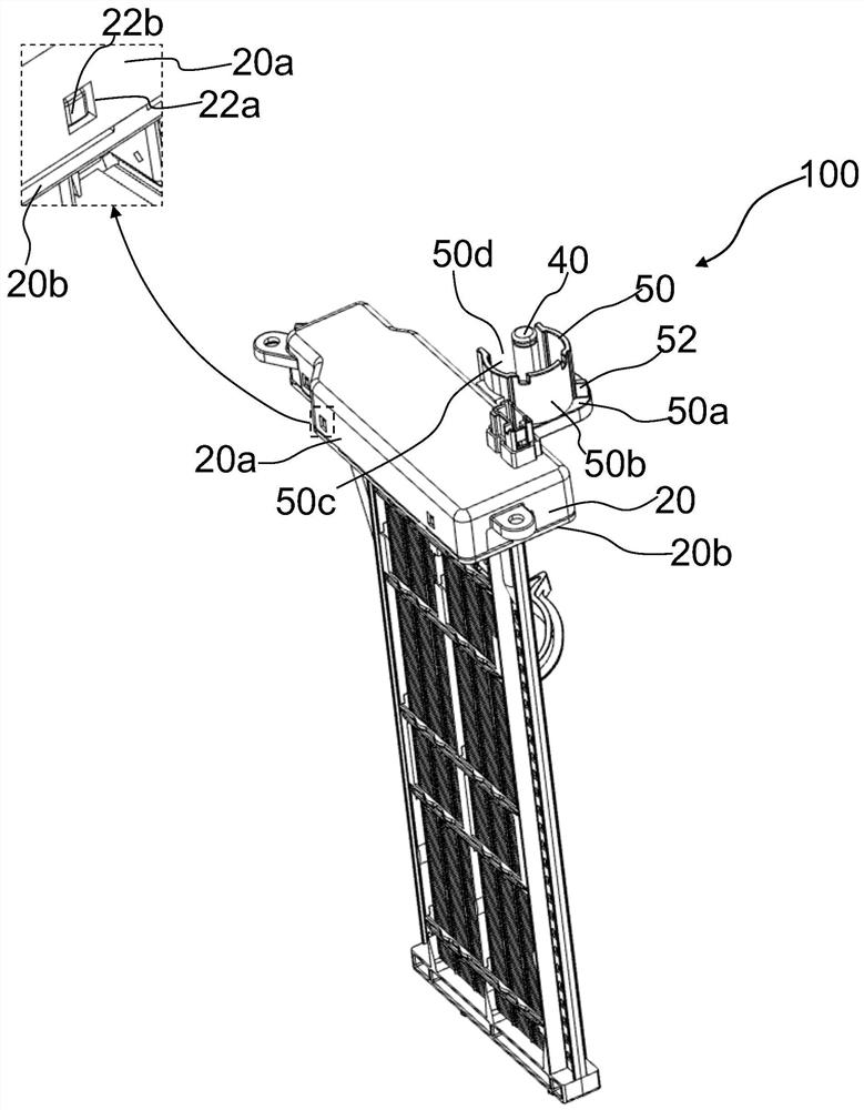
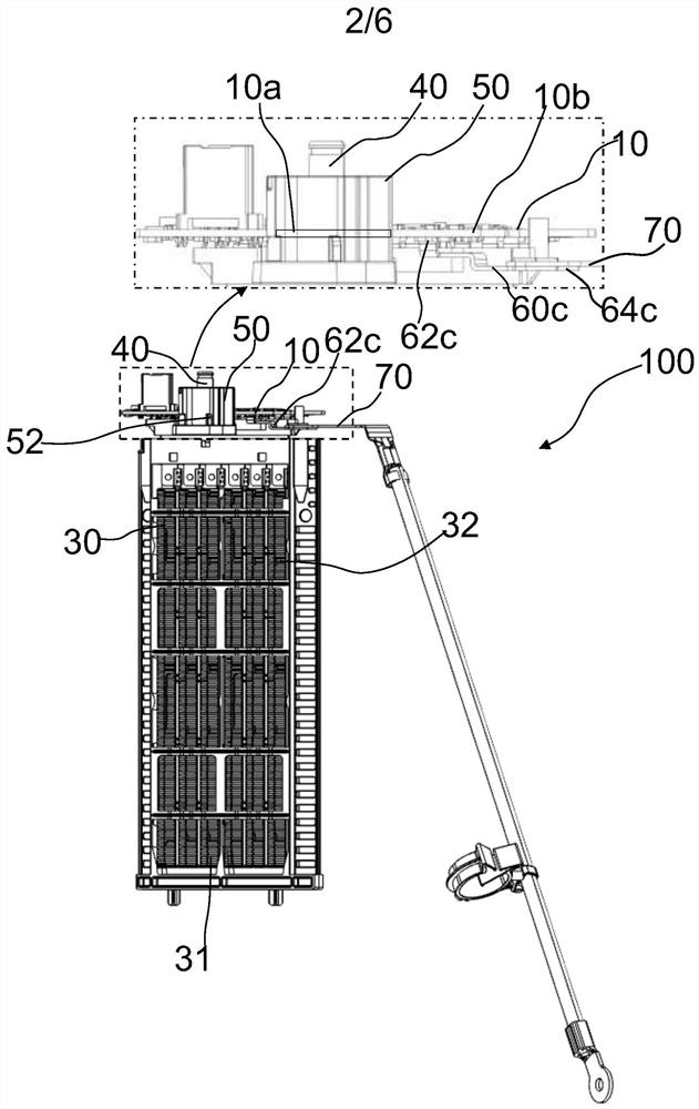
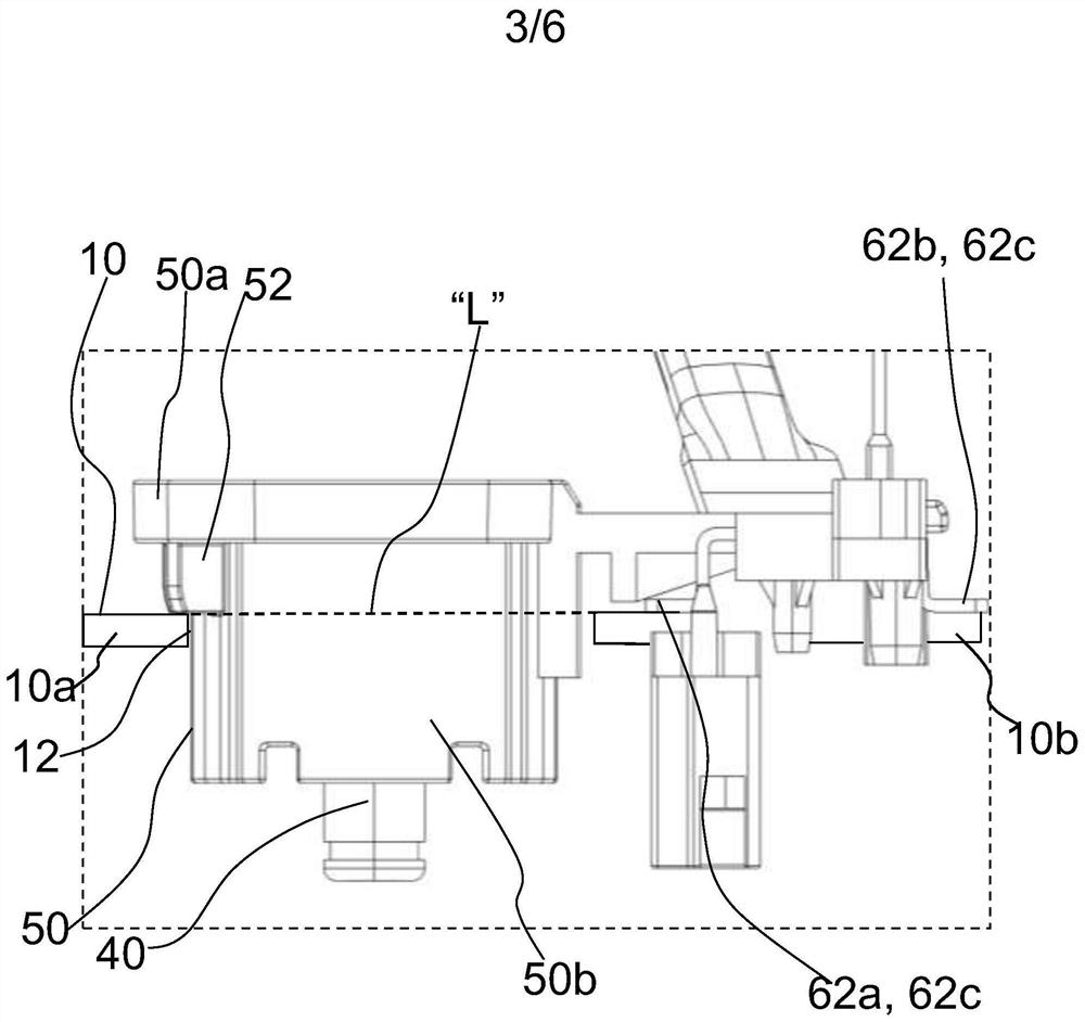
[0035] The present invention envisages a printed circuit board (PCB) controlled heating device, hereafter referred to simply as a heating device. The heating device includes a printed circuit board (PCB) (hereinafter simply referred to as "PCB"), at least one heating element, terminal pins, a terminal board, and a plurality of bus bars. At least a portion of the PCB extends from a printed circuit board (PCB) housing, hereinafter referred to simply as "PCB housing". The plurality of bus bars form a connection between a terminal pin and a terminal board via the at least one heating element. Each bus bar includes at least one first terminal bonded to a printed circuit board (PCB) disposed within the PCB housing and at least...


PUM


Abstract

A heating device comprises a PCB (10), at least one heating element (30, 31, 32), a bus bar (60a, 60b, 60c) and a terminal pin (40) and a terminal plate (70). At least a portion of the PCB (10) extends from the PCB housing (20). The terminal pins (40) are arranged in a connector housing (50), which is at least partially arranged outside the PCB housing (20). The connector housing (50) is providedwith at least one terminal pin. At least one of a portion of the PCB (10) extending from the PCB housing (20) and the connector housing (50) includes at least one support element (52) to support the connector housing (50) relative to the PCB (10) in a predetermined position.

Description

technical field [0001] The present invention relates to a heating device, in particular, the invention relates to a printed circuit board (PCB) controlled heating device for use in a vehicle. Background technique [0002] Typically, high current handling printed circuit boards (PCBs) are traditionally constructed of copper, but printed circuit boards of this construction are expensive. Accordingly, a printed circuit board (PCB) with embedded bus bars is preferred, since this configuration of the bus bar system allows the construction or assembly of different components on the bus bar terminals of the bus bar system. Bus bar terminals distribute power to different components. Also, this configuration of the printed circuit board (PCB) embedding the busbars leads to efficient heat dissipation, notably by combining copper inserts. [0003] The bus bar system includes a plurality of bus bars, wherein each bus bar is formed with at least one first terminal and at least one seco...

Claims


Application Information

Patent Timeline
IPC IPC(8): H05B3/02H01R12/55H01R25/16
CPCH05B3/02H01R12/55H01R25/161H05B3/06H05B2203/02H05B2203/023H05B2203/016H01R13/502
Inventor L·泰利耶童自然耿强肖然刘飞武巧争刘校辉
Owner VALEO AUTOMOTIVE AIR CONDITIONING HUBEI CO LTD
Why Eureka
Try Eureka