Segmented antenna reflector with shield

a technology of segmented reflectors and shields, which is applied in the field of segmented reflector antennas with shields, can solve the problems of shape errors in assembled reflectors, wind load, manufacturing/assembly complexity,

Inactive Publication Date: 2011-12-01
COMMSCOPE TECH LLC
View PDF6 Cites 40 Cited by
  • Summary
  • Abstract
  • Description
  • Claims
  • Application Information

AI Technical Summary

Problems solved by technology

Although smaller reflector segments improve the portability of the resulting antenna, each additional segment interconnection introduces the opportunity for shape errors in the assembled refl...

Method used


Image

  • Segmented antenna reflector with shield
  • Segmented antenna reflector with shield
  • Segmented antenna reflector with shield

Examples


Embodiment Construction

[0022]In the exemplary embodiments herein, the segmented antenna reflector is demonstrated as a generally parabolic circular dish reflector surface for use in, for example, a reflector antenna for terrestrial point-to-point microwave communications. Alternatively, one skilled in the art will recognize that the reflector segment(s) may be formed in a range of other shapes and configurations, for example generally rectangular or elliptical, to form a reflector surface with an alternative shape, such as a planar reflector or an inner or outer toroidal section.

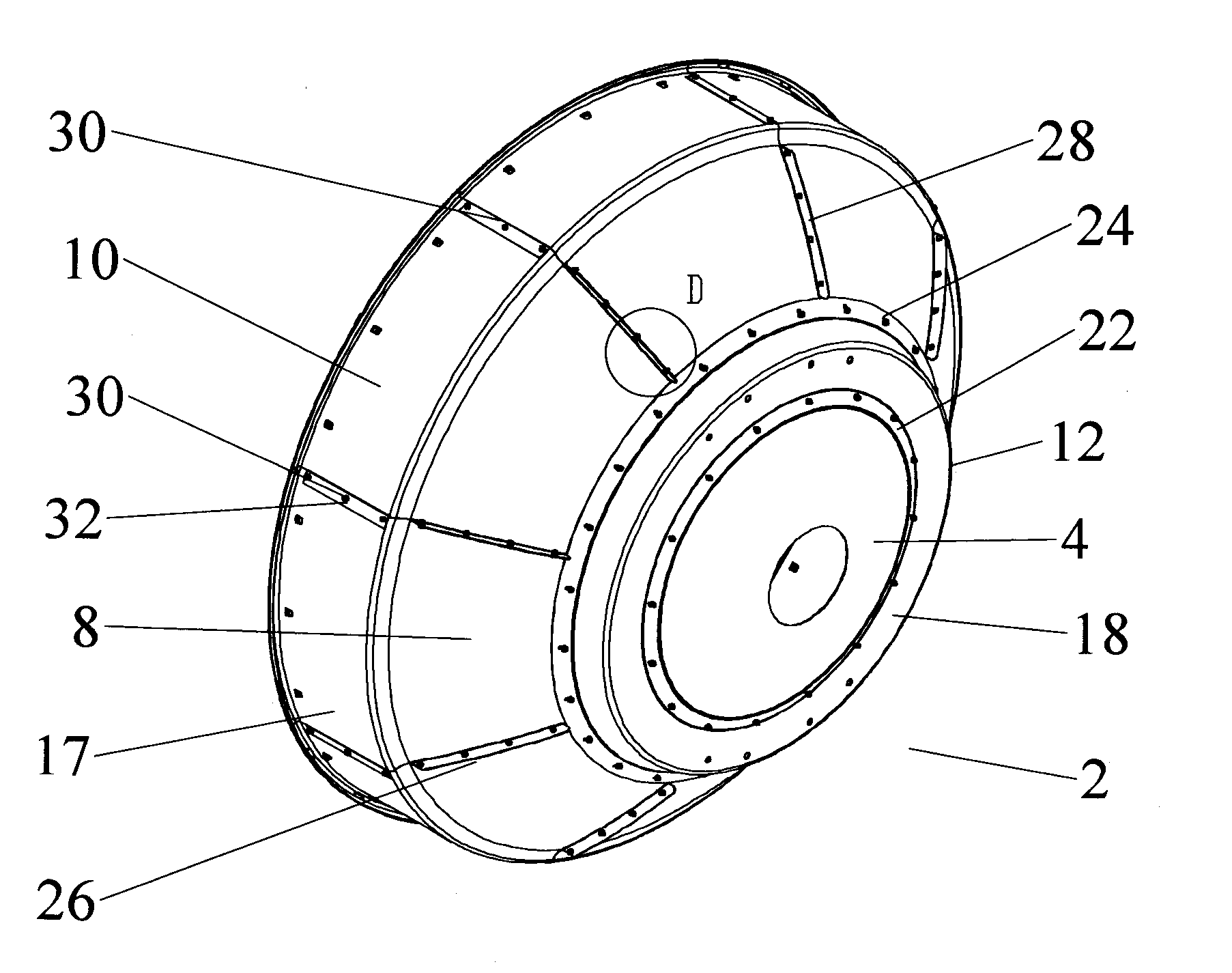
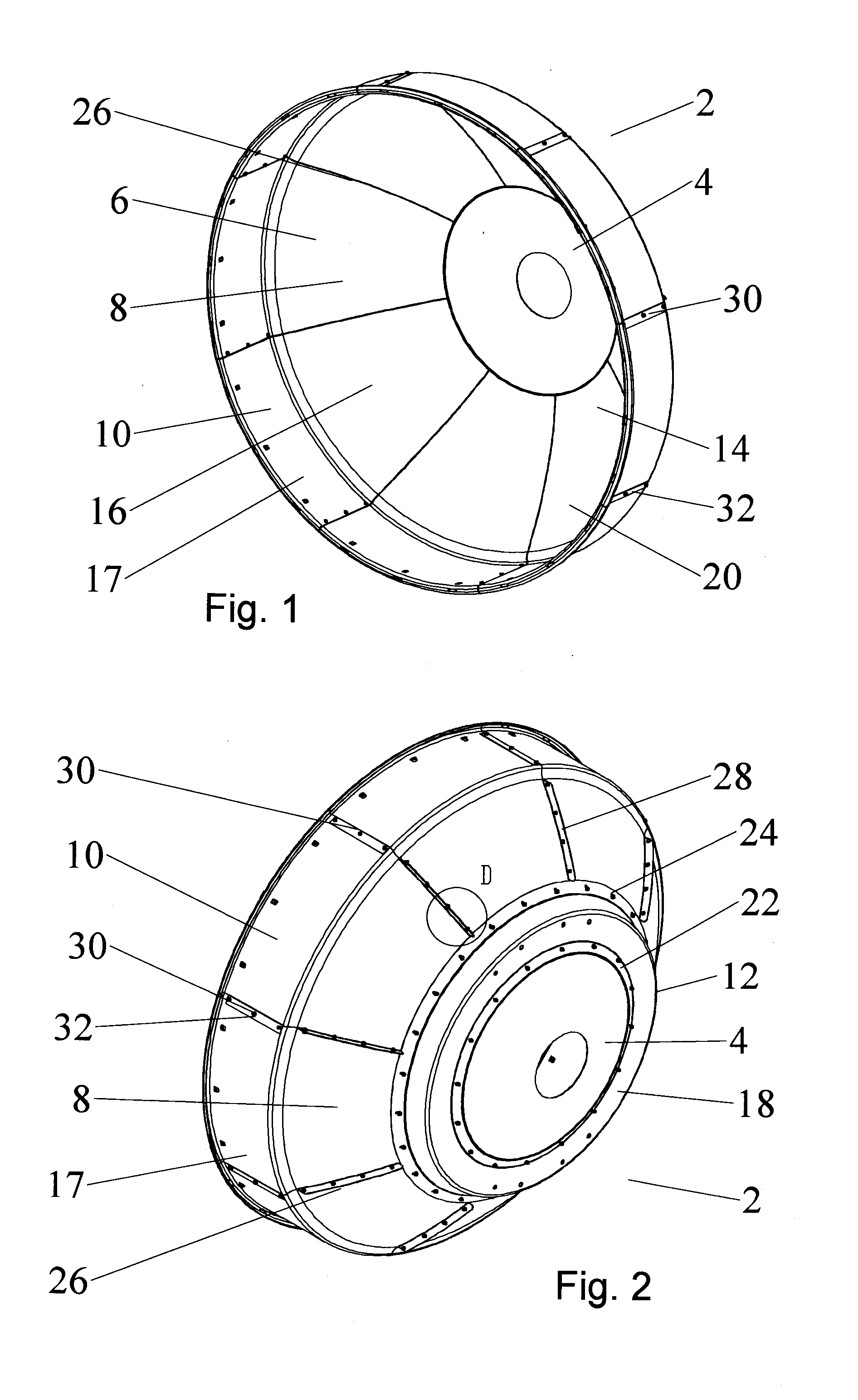
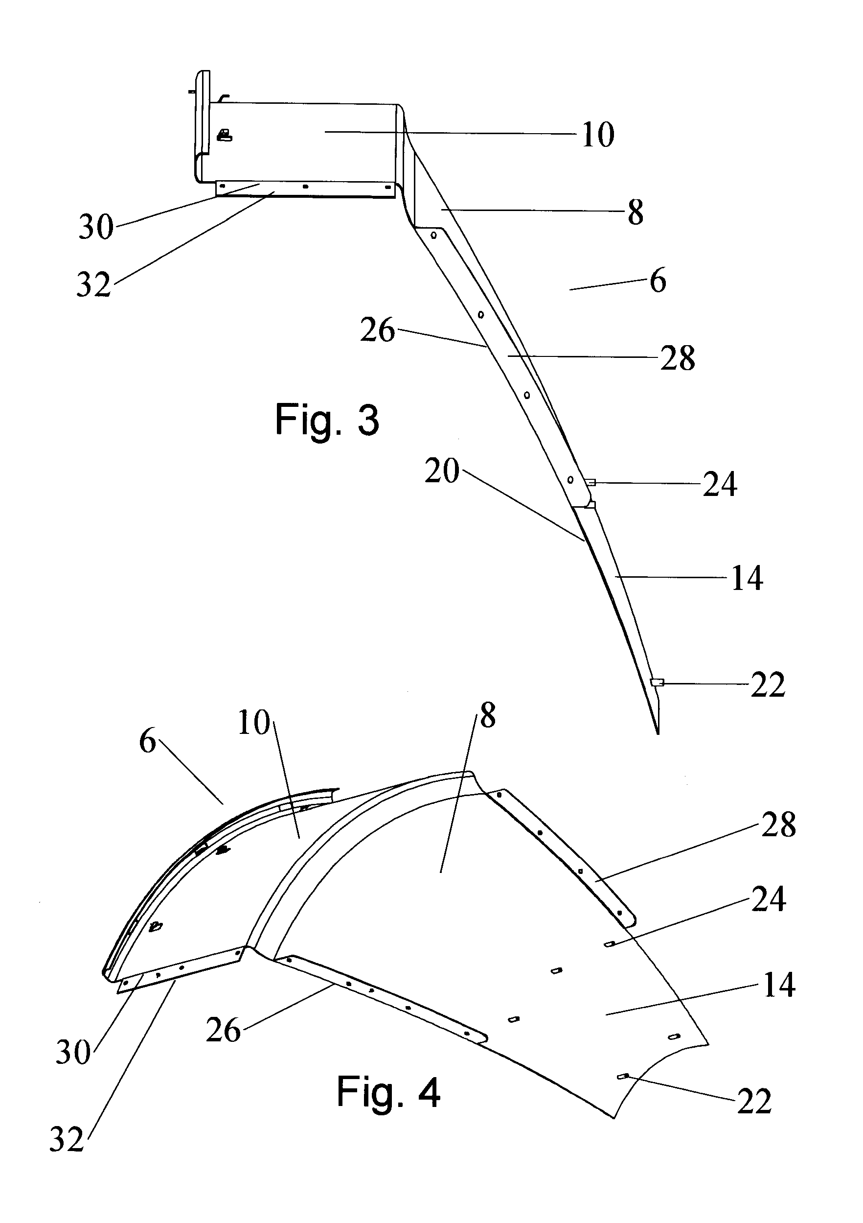
[0023]A first exemplary embodiment of a segmented antenna reflector 2, comprising a central segment 4 with a plurality of peripheral segment(s) 6, each with a reflector portion 8 and a shield portion 10, will now be described with reference to FIGS. 1-2. The central segment 4 is provided with a peripheral coupling portion 12 to which a proximal portion 14 of each peripheral segment 8 is attached.

[0024]The reflector portion(s) 8 ar...


PUM

PropertyMeasurementUnit
Fractionaaaaaaaaaa
Fractionaaaaaaaaaa
Fractionaaaaaaaaaa

Abstract

An antenna reflector includes a central segment with a peripheral coupling portion and a plurality of peripheral segments, each provided with a reflector portion and a shield portion. A proximal portion of each shield portion is dimensioned to couple with the peripheral coupling portion, a reflector portion edge of each peripheral segment is dimensioned to couple with adjacent reflector portion edges and a shield portion edge of each peripheral segment is dimensioned to couple with adjacent shield portion edges. The central segment and the reflector portion of the peripheral segments together form a reflector dish. The shield portions together provide a circumferential shield extending from a periphery of the reflector dish along an antenna boresight of the reflector dish.

Description

BACKGROUND[0001]1. Field of the Invention[0002]This invention relates to reflector antennas. More particularly, the invention relates to a segmented reflector antenna with a shield incorporated with peripheral segments of the reflector dish.[0003]2. Description of Related Art[0004]Reflector Antennas utilize a reflector to concentrate signals upon a subreflector and / or feed assembly. A large reflector concentrates weak signals, enabling low power, high bandwidth signal communications.[0005]Large reflectors may be formed from a plurality of segments that are interconnected to form the desired reflector surface. Although smaller reflector segments improve the portability of the resulting antenna, each additional segment interconnection introduces the opportunity for shape errors in the assembled reflector due to cumulative misalignment and / or warping of the individual segments.[0006]A shield extending forward of the reflector dish may be applied to improve the antenna signal pattern an...

Claims


Application Information

Patent Timeline
IPC IPC(8): H01Q15/14B23P11/00H01P11/00
CPCH01Q1/12H01Q1/526Y10T29/49016Y10T29/49826H01Q15/166
Inventor LEWRY, MATTHEWSIMMS, STEPHENBELL, STEVEN
Owner COMMSCOPE TECH LLC
Why Eureka
Try Eureka