Light emitting device package, light source module, backlight unit, display apparatus, television set, and illumination apparatus

a technology of light emitting devices and backlight units, which is applied in the field of light emitting device packages, light source modules, backlight units, display apparatuses, etc., can solve the problems of slow response speed and low color reproducibility, and the heat emitted by the light emitting element cannot be efficiently discharged, so as to reduce the number of light sources and reduce the optical distance

Active Publication Date: 2011-12-01
SAMSUNG ELECTRONICS CO LTD
View PDF21 Cites 54 Cited by
  • Summary
  • Abstract
  • Description
  • Claims
  • Application Information

AI Technical Summary

Benefits of technology

[0009]One or more embodiments provide a light source module having a diffusion sheet, a reduced optical distance and a reduced number of light sources, a display device having the light source module, and an illumination apparatus including the light source module.

Problems solved by technology

In particular, a light source unit for efficiently emitting heat generated in a light emitting element such as an LED to the outside is desirable, as a resin part or lens unit encapsulating the light emitting element may be degraded and this defect may become more serious with the use of high-power light emitting elements in a case in which the heat emitted by the light emitting element can not be efficiently discharged.
However, CCFLs use mercury gas, having disadvantages in that it has a slow response speed and low color reproducibility (or a color gamut) and is not suitable for a light, thin, short, and small LCD panel.
However, as light emitting diodes are a point light sources, hot spots may occur from backlight modules employing LEDs, whereby it may be difficult to provide uniform illumination with respect to the emitting surface of the backlight module

Method used


Image

  • Light emitting device package, light source module, backlight unit, display apparatus, television set, and illumination apparatus
  • Light emitting device package, light source module, backlight unit, display apparatus, television set, and illumination apparatus
  • Light emitting device package, light source module, backlight unit, display apparatus, television set, and illumination apparatus

Examples


Embodiment Construction

[0078]Exemplary embodiments will now be described in detail with reference to the accompanying drawings. The invention may, however, be embodied in many different forms and should not be construed as limited to the embodiments set forth herein. Rather, these embodiments are provided so that this disclosure will be thorough and complete, and will fully convey the scope of the invention to those skilled in the art. In the drawings, the shapes and dimensions may be exaggerated for clarity, and the same reference numerals will be used throughout to designate the same or like components.

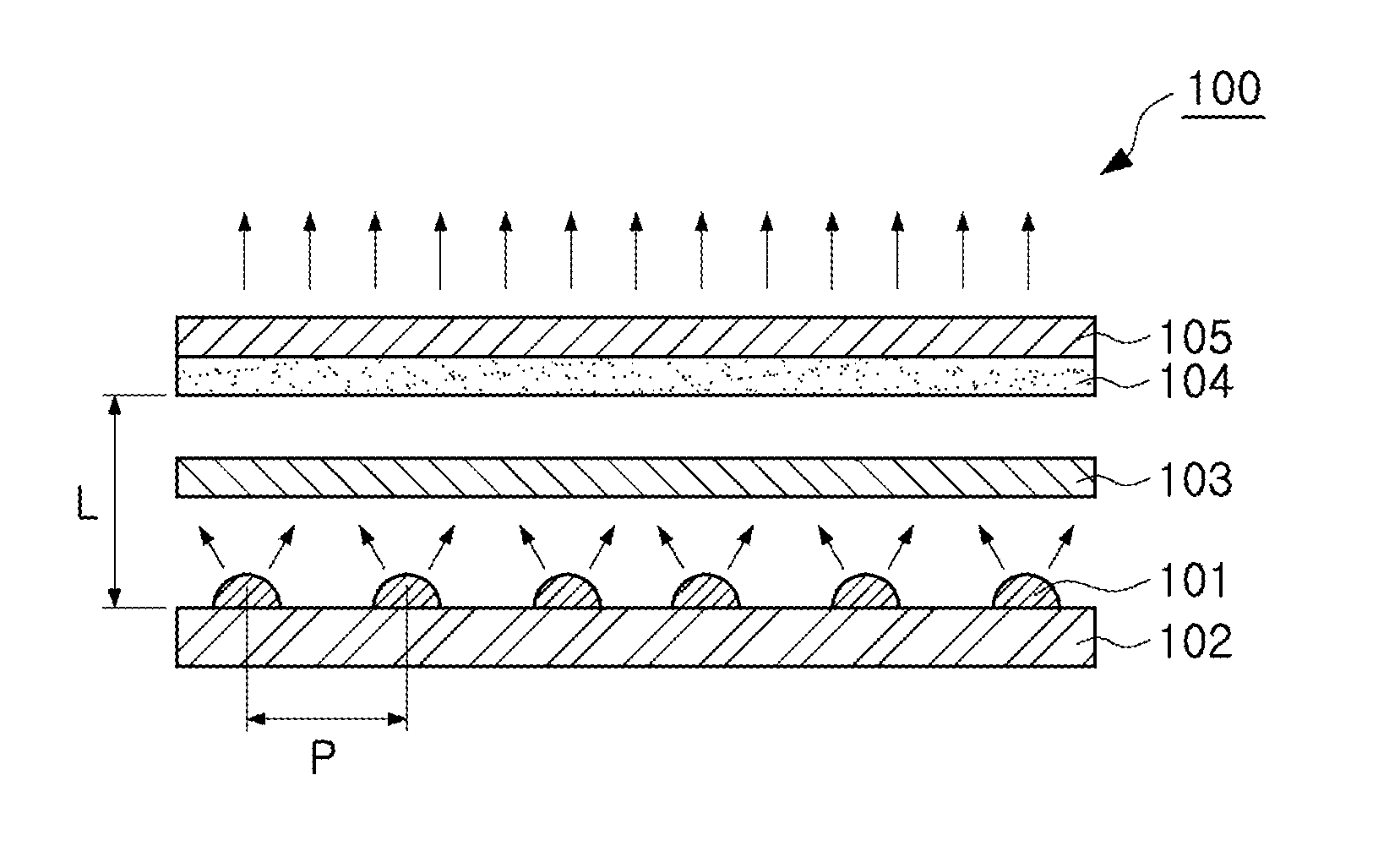
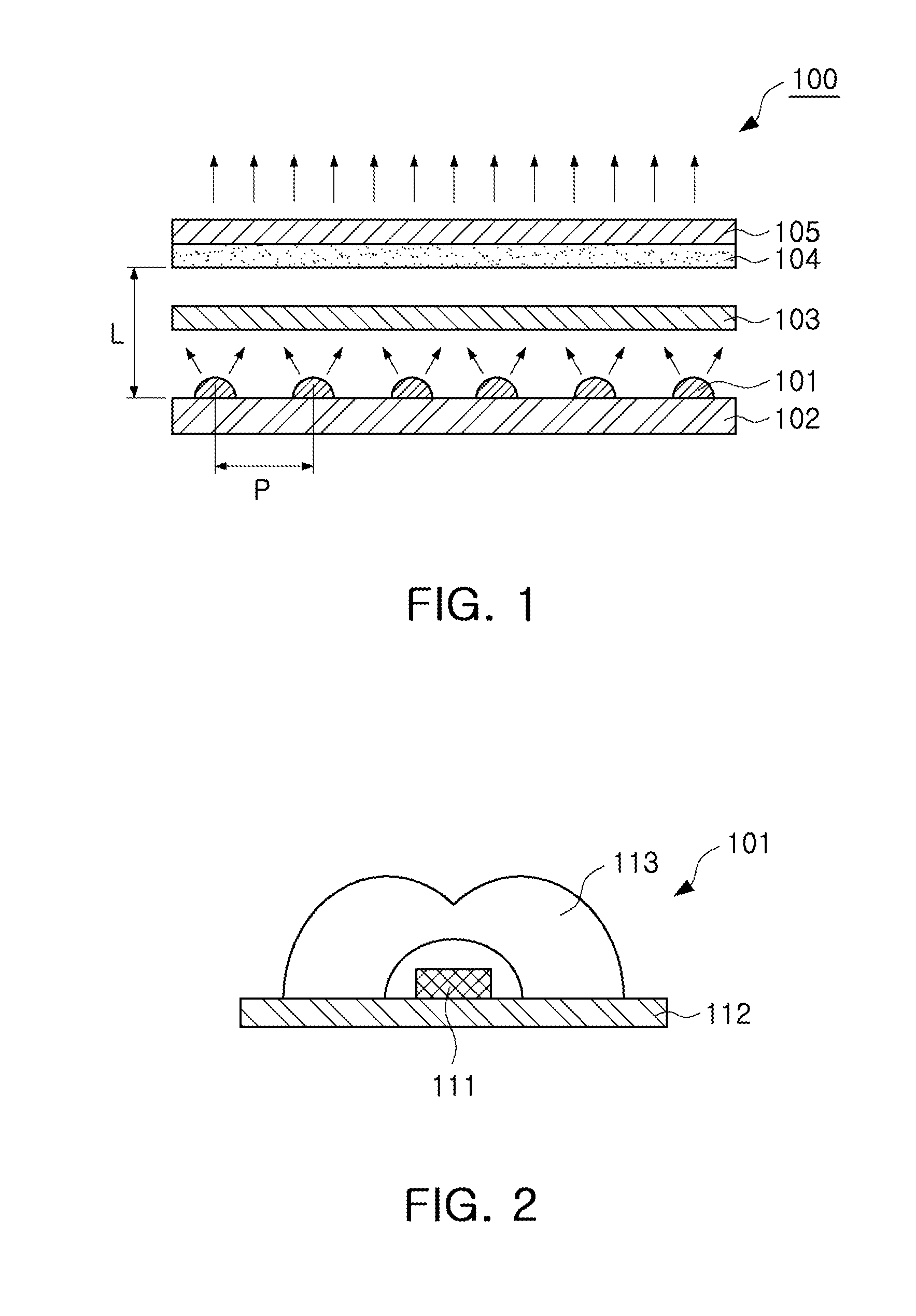
[0079]With reference to FIG. 1, a light source module 100 includes a light source unit 101 and an optical sheet 103, and further includes a circuit board 102 on which the light source unit 101 is mounted, and a diffusion sheet 104 and a luminance enhancement sheet 105 disposed at an upper side of the optical sheet 103.

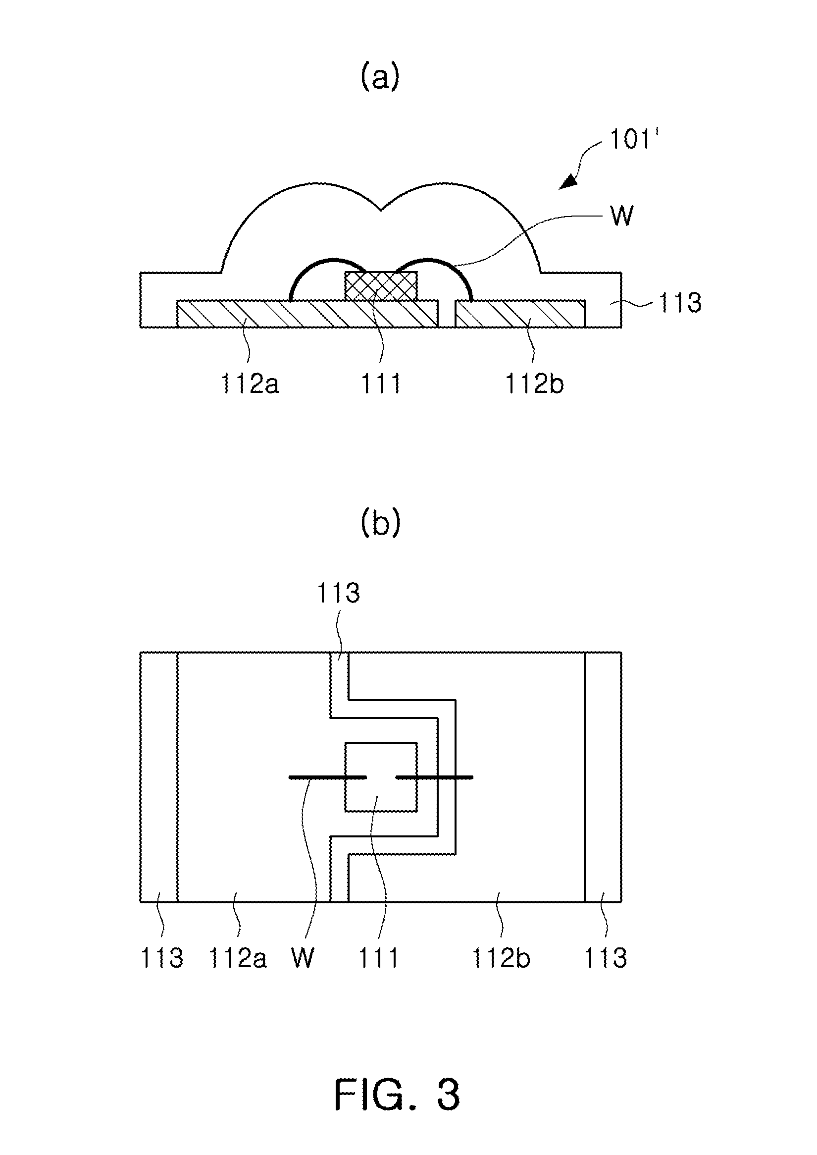
[0080]As shown in FIG. 2, the light source unit 101 may include a light emitting element...


PUM

PropertyMeasurementUnit
radiation angleaaaaaaaaaa
orientation angleaaaaaaaaaa
radiation angleaaaaaaaaaa

Abstract

A light source module, a backlight unit, a display apparatus, a television set, and an illumination apparatus are provided. The light source module includes: one or more light source units including a light emitting element emitting light when electricity is applied thereto; and an optical sheet disposed above the light source units and exhibiting bidirectional transmittance distribution function characteristics having first and second peaks at radiation angles less than 0° and greater than 0°.

Description

CROSS-REFERENCE TO RELATED APPLICATIONS[0001]This application claims priority from Korean Patent Application No. 10-2010-0040789 filed on Apr. 30, 2010 in the Korean Intellectual Property Office, Korean Patent Application No. 10-2010-0134748 filed on Dec. 24, 2010 in the Korean Intellectual Property Office, and Korean Patent Application No. 10-2011-0016427 filed on Feb. 24, 2011, in the Korean Intellectual Property Office, the disclosures of which are incorporated herein by reference in their entirety.BACKGROUND[0002]1. Field[0003]Apparatuses consistent with exemplary embodiments relate to a light emitting device package, a light source module, a backlight unit, a display apparatus, a television set, and an illumination apparatus.[0004]2. Description of the Related Art[0005]A light emitting diode (LED), a type of semiconductor light emitting device, is a semiconductor device capable of generating light of various colors according to a recombination of electrons and holes at p and n ...

Claims


Application Information

Patent Timeline
Patent Type & Authority Applications(United States)
IPC IPC(8): H04N5/66F21V5/00G02F1/13357F21V11/00
CPCH01L2224/48091H01L2224/48247G02F1/133606H01L2224/8592G02B19/0014G02B19/0071G02F1/133603H01L33/58H01L2224/48257G02B19/0061H01L2924/00014F21Y2115/10F21K9/60H01L2924/181H01L2924/00012H01L33/52H01L33/62F21V11/00
Inventor PARK, JUNG KYUPARK, YOUNG SAMCHOI, SUNG A.LIM, JEONG EUNKIM, JIN MOHONG, MAN KIHAN, TAE HEONSHIN, CHURL WUNGKIM, YOUNG TAEKHONG, DAE WOONJUN, YOUNG GEUNKOOK, JUNG KYU
Owner SAMSUNG ELECTRONICS CO LTD
Why Eureka
Try Eureka