Optical Image Capturing System

a technology of optical image and capturing system, which is applied in the field of compact, can solve the problems of deterioration of quality in peripheral image formation, difficulty in manufacturing, and distortion rate in image formation, and achieve the effects of reducing the height of the optical system, reducing the back focal distance of the optical image capturing system, and good imaging quality

Active Publication Date: 2017-11-02
ABILITY OPTO ELECTRONICS TECH
View PDF2 Cites 8 Cited by
  • Summary
  • Abstract
  • Description
  • Claims
  • Application Information

AI Technical Summary

Benefits of technology

[0031]The optical image capturing system described above is applicable to the demand of video recording with above millions or ten millions-pixels (e.g. 4K and 2K videos or the so-called UHD and QHD) and leads to a good imaging quality.
[0032]The height of optical system (HOS) may be reduced to achieve the minimization of the optical image capturing system when the absolute value of f1 is larger than f1 (|f1|>f4).
[0033]When the relationship |f2|+|f3|>|f1|+|f4| is satisfied, at least one of the second through third lens elements may have weak positive refractive power or weak negative refractive power. The weak refractive power indicates that an absolute value of the focal length of a specific lens element is greater than 10. When at least one of the second through third lens elements has the weak positive refractive power, the positive refractive power of the first lens element can be shared, such that the unnecessary aberration will not appear too early. On the contrary, when at least one of the second and third lens elements has the weak negative refractive power, the aberration of the optical image capturing system can be corrected and fine-tuned.
[0034]The fourth lens element may have negative refractive power, and the image-side surface thereof may be a concave surface. With this configuration, the back focal distance of the optical image capturing system may be shortened and the system may be minimized. Besides, at least one surface of the fourth lens element may possess at least one inflection point, which is capable of effectively reducing the incident angle of the off-axis rays of the field of view, thereby further correcting the off-axis aberration.

Problems solved by technology

But the optical image capturing system with the large aperture design often produces more aberration, resulting in the deterioration of quality in peripheral image formation and difficulties of manufacturing, and the optical image capturing system with wide view angle design increases distortion rate in image formation, thus the optical image capturing system in prior arts cannot meet the requirement of the higher order camera lens module.
Therefore, how to effectively increase quantity of incoming light and view angle of the optical lenses, not only further improves total pixels and imaging quality for the image formation, but also considers the equity design of the miniaturized optical lenses, becomes a quite important issue.

Method used


Image

  • Optical Image Capturing System
  • Optical Image Capturing System
  • Optical Image Capturing System

Examples


first embodiment

The First Embodiment

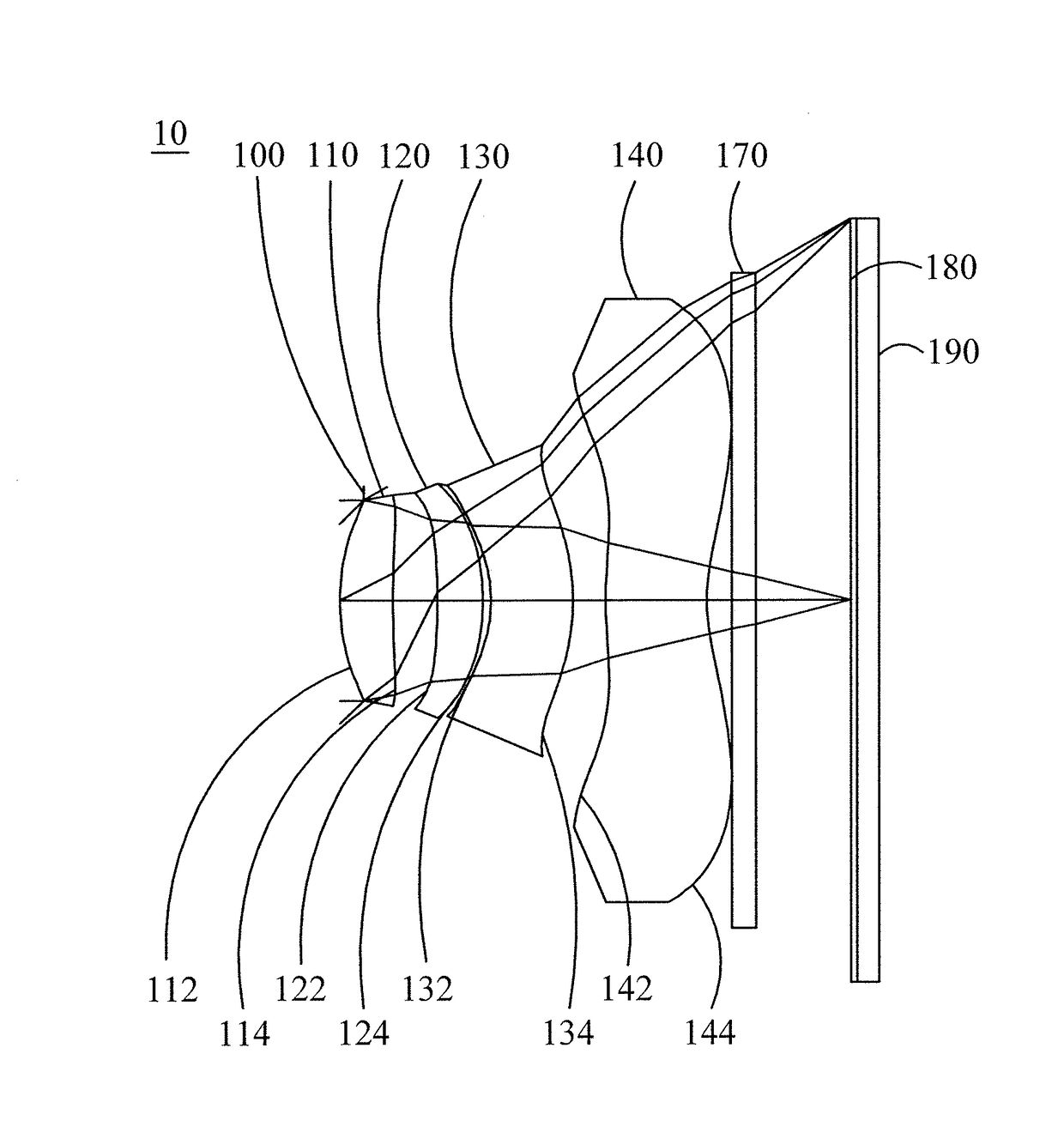
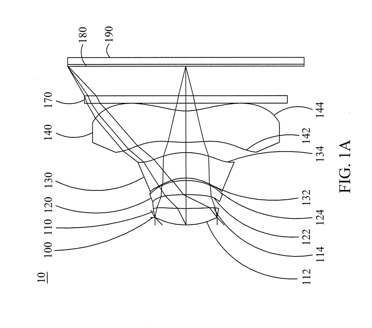
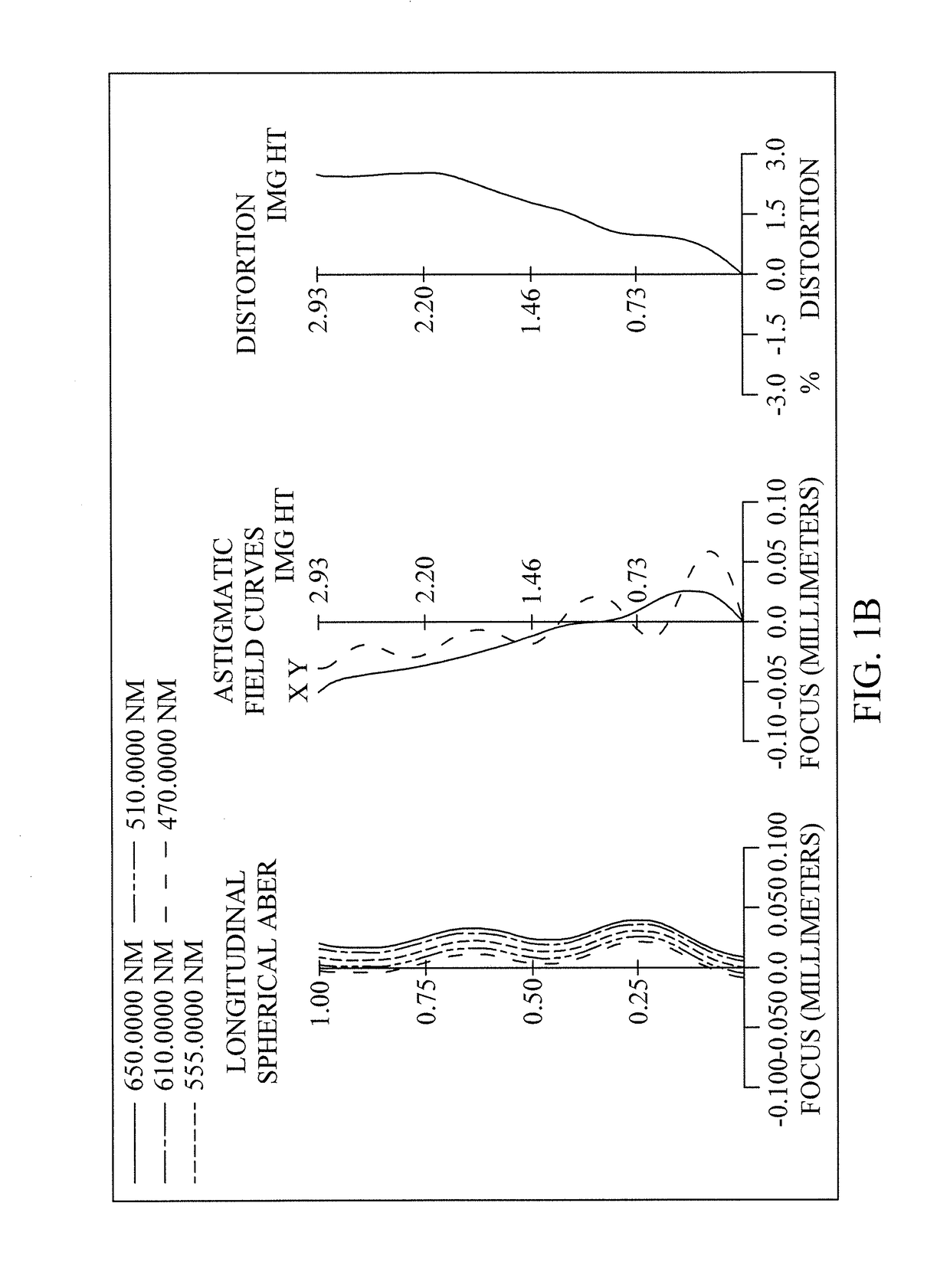
[0092]Please refer to FIG. 1A to FIG. 1C. FIG. 1A is a schematic view of the optical image capturing system according to the first embodiment of the present invention. FIG. 1B shows the longitudinal spherical aberration curves, astigmatic field curves, and an optical distortion grid of the optical image capturing system in the order from left to right according to the first embodiment of the present invention. FIG. 1C is a transverse aberration diagram of the longest operation wavelength and the shortest operation wavelength for tangential fan and sagittal fan, wherein the longest operation wavelength and the shortest operation wavelength pass through an edge of the entrance pupil and incident at the position of 0.7 HOI on the image plane, according to the first embodiment of the present invention. As shown in FIG. 1A, in the order from an object side to an image side, the optical image capturing system includes an aperture stop 100, a first lens element 110, a s...

second embodiment

[0134]Please refer to FIG. 2A, FIG. 2B and FIG. 2C. FIG. 2A is a schematic view of the optical image capturing system according to the second embodiment of the present invention. FIG. 2B shows the longitudinal spherical aberration curves, astigmatic field curves, and an optical distortion grid of the optical image capturing system of the second embodiment, in the order from left to right. FIG. 2C is a transverse aberration diagram of the longest operation wavelength and the shortest operation wavelength for tangential fan and sagittal fan, wherein the longest operation wavelength and the shortest operation wavelength pass through an edge of the aperture stop and incident at the position of 0.7 HOI on the image plane, according to optical image capturing system of the second embodiment. As shown in FIG. 2A, in the order from an object side to an image side, the optical image capturing system includes a first lens element 210, an aperture stop 200, a second lens element 220, a third l...

third embodiment

[0145]Please refer to FIG. 3A to FIG. 3C. FIG. 3A is a schematic view of the optical image capturing system according to the third embodiment of the present invention. FIG. 3B shows the longitudinal spherical aberration curves, astigmatic field curves, and an optical distortion grid of the optical image capturing system, in the order from left to right, according to the third embodiment of the present invention. FIG. 3C is a transverse aberration diagram of the longest operation wavelength and the shortest operation wavelength for tangential fan and sagittal fan, wherein the longest operation wavelength and the shortest operation wavelength pass through an edge of the aperture stop and incident at the position of 0.7 HOI on the image plane, according to the third embodiment of the present invention. As shown in FIG. 3A, in the order from an object side to an image side, the optical image capturing system includes a first lens element 310, an aperture stop 300, a second lens element ...


PUM


Abstract

A four-piece optical lens for capturing image and a five-piece optical module for capturing image are provided. In the order from an object side to an image side, the optical lens along the optical axis includes a first lens with positive refractive power; a second lens with refractive power; a third lens with refractive power; and a fourth lens with refractive power; and at least one of the image-side surface and object-side surface of each of the four lens elements are aspheric. The optical lens can increase aperture value and improve the imagining quality for use in compact cameras.

Description

CROSS-REFERENCE TO RELATED APPLICATION[0001]This application claims priority from Taiwan Patent Application No. 105113328, filed on Apr. 28, 2016, in the Taiwan Intellectual Property Office, the content of which is hereby incorporated by reference in its entirety for all purposes.BACKGROUND OF THE INVENTION1. Field of the Invention[0002]The present disclosure relates to an optical image capturing system, and more particularly to a compact optical image capturing system which can be applied to electronic products.2. Description of the Related Art[0003]In recent years, with the rise of portable electronic devices having camera functionalities, the demand for an optical image capturing system is raised gradually. The image sensing device of ordinary photographing camera is commonly selected from charge coupled device (CCD) or complementary metal-oxide semiconductor sensor (CMOS Sensor). In addition, as advanced semiconductor manufacturing technology enables the minimization of pixel si...

Claims


Application Information

Patent Timeline
Patent Type & Authority Applications(United States)
IPC IPC(8): G02B13/00G02B9/34G02B7/04G02B27/64G02B27/00G02B5/20
CPCG02B13/004G02B9/34G02B5/20G02B27/646G02B27/0025G02B7/04G02B13/18
Inventor LAI, CHIEN-HSUNTANG, NAI-YUANCHANG, YEONG-MING
Owner ABILITY OPTO ELECTRONICS TECH
Why Eureka
Try Eureka