Interference measurement apparatus and method for measuring interference

a measurement apparatus and interference technology, applied in the field of interference measurement apparatus and method, can solve the problems of difficult to obtain a clear reconstructed image of the subject, less accurate obtained positional information, and many errors

Inactive Publication Date: 2011-12-01
NAT UNIV KYOTO INST OF TECH
View PDF12 Cites 36 Cited by
  • Summary
  • Abstract
  • Description
  • Claims
  • Application Information

AI Technical Summary

Benefits of technology

[0026]An interference measurement apparatus of the present invention includes: at least one light source which generates coherent light; a light splitting section which splits, into a reference light beam and an object light beam, the coherent light emitted from the at least one light source; an image-capturing section which captures an interference image formed by the reference light beam and the object light beam which has reached the image-capturing section via a subject; a polarization splitting section which splits, into two types of object light beams which are different in polarization direction, the object light beam emitted from the light splitting section, so that an angular difference is caused between respective propagation directions of the two types of object light beams; and a polarizer array section which allows (i) the reference light beam and (ii) the two types of

Problems solved by technology

This makes it difficult to obtain a clear reconstructed image of the subject 111.
As a

Method used


Image

  • Interference measurement apparatus and method for measuring interference
  • Interference measurement apparatus and method for measuring interference
  • Interference measurement apparatus and method for measuring interference

Examples


first embodiment

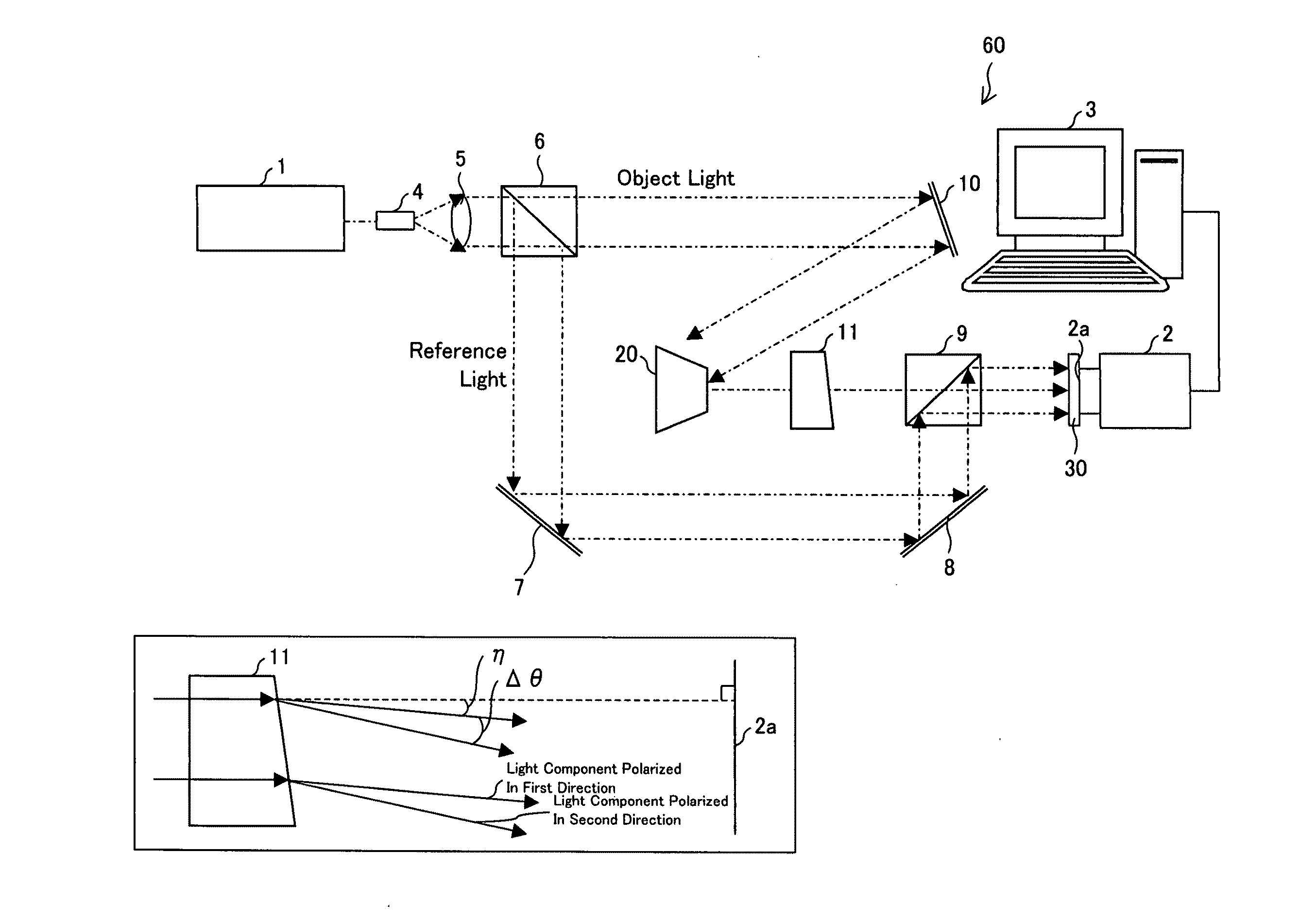
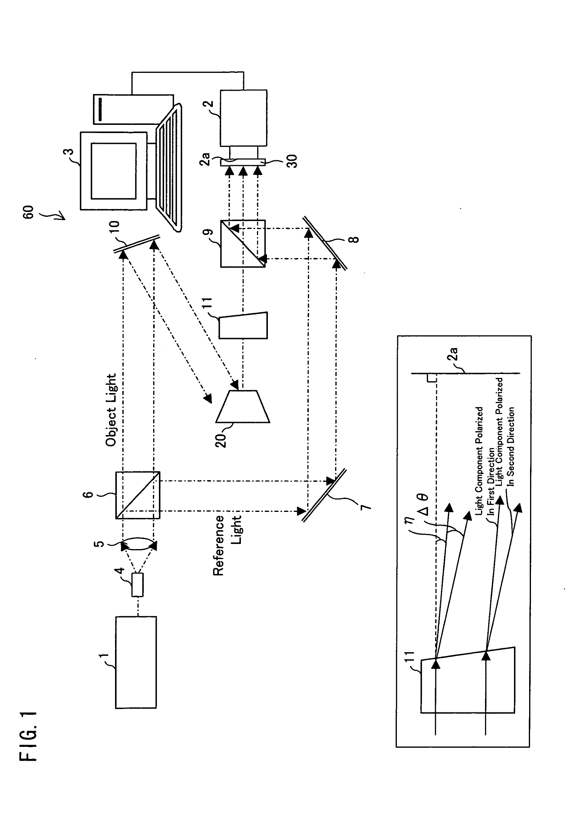
[0082]FIG. 1 is a schematic view illustrating an arrangement of a digital holography apparatus (interference measurement apparatus) 60 of a first embodiment. The digital holography apparatus 60 includes an image-capturing apparatus having (i) an optical system which includes a laser light source (light source) 1, and (ii) an image-capturing element (image-capturing section) having an image-capturing plane 2a which image-capturing element is a CCD. The digital holography apparatus 60 further includes a calculator (reproducer section) 3 connected to an output of the image-capturing element 2.

[0083]The laser light source 1 generates coherent light, i.e., a laser beam. A direction perpendicular to a propagation direction of the laser beam is defined as a first direction, and a direction perpendicular to each of the propagation direction and the first direction is defined as a second direction. The laser beam is linearly-polarized light having a light component polarized in the first dir...

second embodiment

[0104]The following describes a digital holography apparatus which includes an in-line optical system. For convenience of explanation, members and arrangements which have same functions as those in drawings described in the first embodiment are given common reference signs, and descriptions of such members and arrangements are not repeated below.

[0105]FIG. 4 is a schematic view illustrating an arrangement of a digital holography apparatus (interference measurement apparatus) 61 of a second embodiment. The digital holography apparatus 61 includes an in-line optical system. An optical axis of a reference light beam which is incident upon an image-capturing plane 2a is perpendicular to the image-capturing plane 2a. A subject 20 is located optically right in front of the image-capturing plane 2a. It follows that a reconstructed image obtained by carrying out Frestnel transformation with respect to an interference pattern is made up of a zeroth-order diffraction image and a ±first-order ...

third embodiment

[0136]The following describes a digital holography apparatus of a third embodiment. For convenience of explanation, members and arrangements which have same functions as those in drawings described in the second embodiment are given common reference signs, and descriptions of such members and arrangements are not repeated below.

[0137]FIG. 12 is a schematic view illustrating an arrangement of a digital holography apparatus (interference measurement apparatus) 62 of the third embodiment. The digital holography apparatus 62 includes an in-line optical system. An optical axis of a reference light beam which is incident upon an image-capturing plane 2a is perpendicular to the image-capturing plane 2a. A subject 22 is located optically right in front of the image-capturing plane 2a. This means that as viewed from the image-capturing element 2, the subject 22 looks as if the subject 22 is located right in front of the image-capturing element 2 since light from the subject 22 is reflected b...


PUM


Abstract

An embodiment of the present invention realizes an interference measurement apparatus which can obtain an interference image to be used for obtaining three-dimensional information of a subject which dynamically changes. An interference measurement apparatus of the present invention, which captures an interference image formed by the reference light beam and the object light beam which has reached the image-capturing element via a subject, the interference measurement apparatus includes: a laser light source; a beam splitter which splits a laser beam into a reference light beam and an object light beam; and an image-capturing element; a polarization splitting section which splits the object light beam into two types of object light beams which are different in polarization direction so that an angular difference is caused between respective propagation directions of the two types of object light beams; and a polarizer array device which allows (i) the reference light beam and (ii) the two types of object light beams which have reached the polarizer array device via the subject to pass through the polarizer array device (30), the polarizer array device in which a plurality of first polarizer regions and a plurality of second polarizer regions are arranged, and each of the plurality of first polarizer regions and each of the plurality of second polarizer regions respectively allowing light components which are different in polarization direction. This makes it possible to obtain, by one-time image capturing, a plurality of interference patterns required for phase unwrapping.

Description

TECHNICAL FIELD[0001]The present invention relates to (i) an interference measurement apparatus which measures an interference image formed by interference between a reference light beam and an object light beam so as to measure a shape of a subject, and to (ii) a method for measuring interference.BACKGROUND ART[0002]Hereinafter, phases are expressed in radians. With increase of accuracy and variety of processing techniques, advanced measurement and analysis of a three-dimensional shape etc. of an object are sought after. Accordingly, various measurement methods have been developed. Among such measurement method, interference measurement techniques utilizing light interference, especially, digital holography makes it possible to obtain three-dimensional information of an object in a non-contact and non-destructive manner. Accordingly, digital holography is one of measurement methods which receive attention recently.[0003]Digital holography is a technique for reproducing an image of ...

Claims


Application Information

Patent Timeline
IPC IPC(8): G01B9/021
CPCG01B9/021G01B11/2441G03H1/0443G03H1/041G03H2001/0458G03H2222/31G03H1/08G03H2001/0452
Inventor AWATSUJI, YASUHIROTAHARA, TATSUKI
Owner NAT UNIV KYOTO INST OF TECH
Why Eureka
Try Eureka