Head mounted display

a display and head technology, applied in the field of head mounted displays, can solve the problems of difficult to reduce the size of the head mounted display, the reduction of the hmd in size cannot be achieved, and the difficulty of sufficiently reducing the hmd in size, so as to achieve easy arranging, high accuracy, and high accuracy

Active Publication Date: 2011-12-01
SEIKO EPSON CORP
View PDF0 Cites 17 Cited by
  • Summary
  • Abstract
  • Description
  • Claims
  • Application Information

AI Technical Summary

Benefits of technology

[0007]An advantage of some aspects of the invention is to provide an HMD which is easily manufactured and is sufficiently reduced in size.
[0010]Further, the optical unit is formed by integrating the planoconvex lens and the half mirror. Therefore, the planoconvex lens and the half mirror can be easily arranged with high accuracy. Since the light split by the half mirror is collimated, the planoconvex lens and the half mirror do not need to be arranged with high accuracy.
[0011]Further, that the light split by the half mirror is collimated indicates that the planoconvex lens and the half mirror can be arranged close to each other. The curvature of the second convex surface at the fourth end is larger than that at the third end. The curvature of the concave mirror at the first end is larger than that at the second end. Therefore, a distance between the display unit and the second end of the concave mirror can be sufficiently shortened.
[0012]Therefore, with the aspect of the invention, an HMD which is easily manufactured and is sufficiently reduced in size can be provided. Further, according to the aspect of the invention, the light incident on the transparent base body reaches the half mirror without being output from the transparent base body. Accordingly, light can be prevented from being attenuated.
[0013]In the above configuration, it is preferable that the curvature of the concave mirror be gradually increased from the second end to the first end. Further, it is preferable that the curvature of the second convex surface be gradually increased from the third end to the fourth end. In this case, an image can be easily projected with high quality. Further, in the above configuration, it is preferable that each of the first optical system and the second optical system include a plurality of optical units. In this case, various adjustments such as adjustment of an angle of view can be easily made.

Problems solved by technology

Therefore, it is difficult to reduce the head mounted display in size.
That is to say, although the number of displays is reduced, reduction of the HMD in size can barely be achieved.
That is to say, it is difficult to sufficiently reduce the HMD in size.
Therefore, the HMD is not easily manufactured.

Method used


Image

  • Head mounted display
  • Head mounted display
  • Head mounted display

Examples


first embodiment

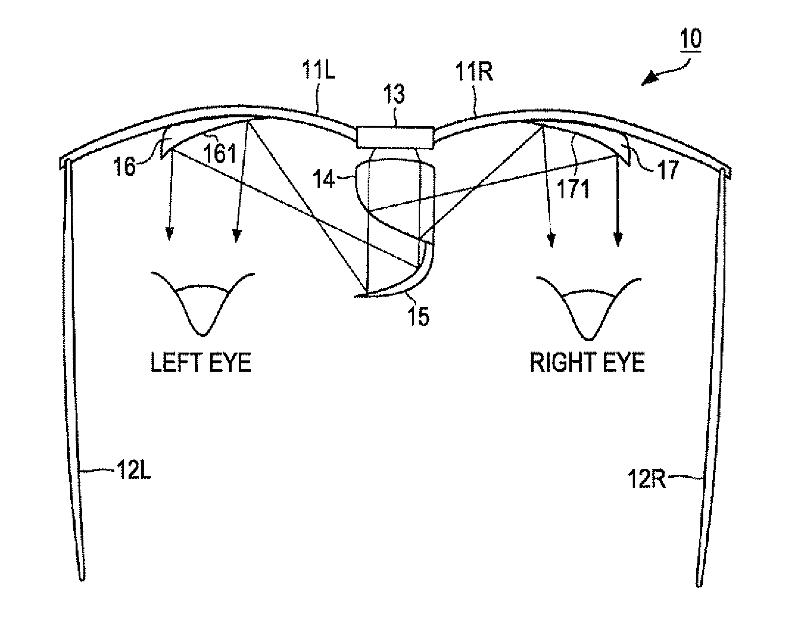
[0021]FIG. 1 is a plan view illustrating an HMD 10 according to the first embodiment of the invention. The HMD 10 is an eyeglass-shaped display apparatus, which is to be mounted on a person's head. The HMD 10 includes a lens 11L corresponding to the left eye, a lens 11R corresponding to the right eye, a temple portion 12L which rests on the left ear and a temple portion 12R which rests on the right ear. Although the lenses 11L and 11R may be transparent, the lenses 11L and 11R are opaque in this embodiment. The temple portion 12L is attached to the left end of the lens 11L and the temple portion 12R is attached to the right end of the lens 11R.

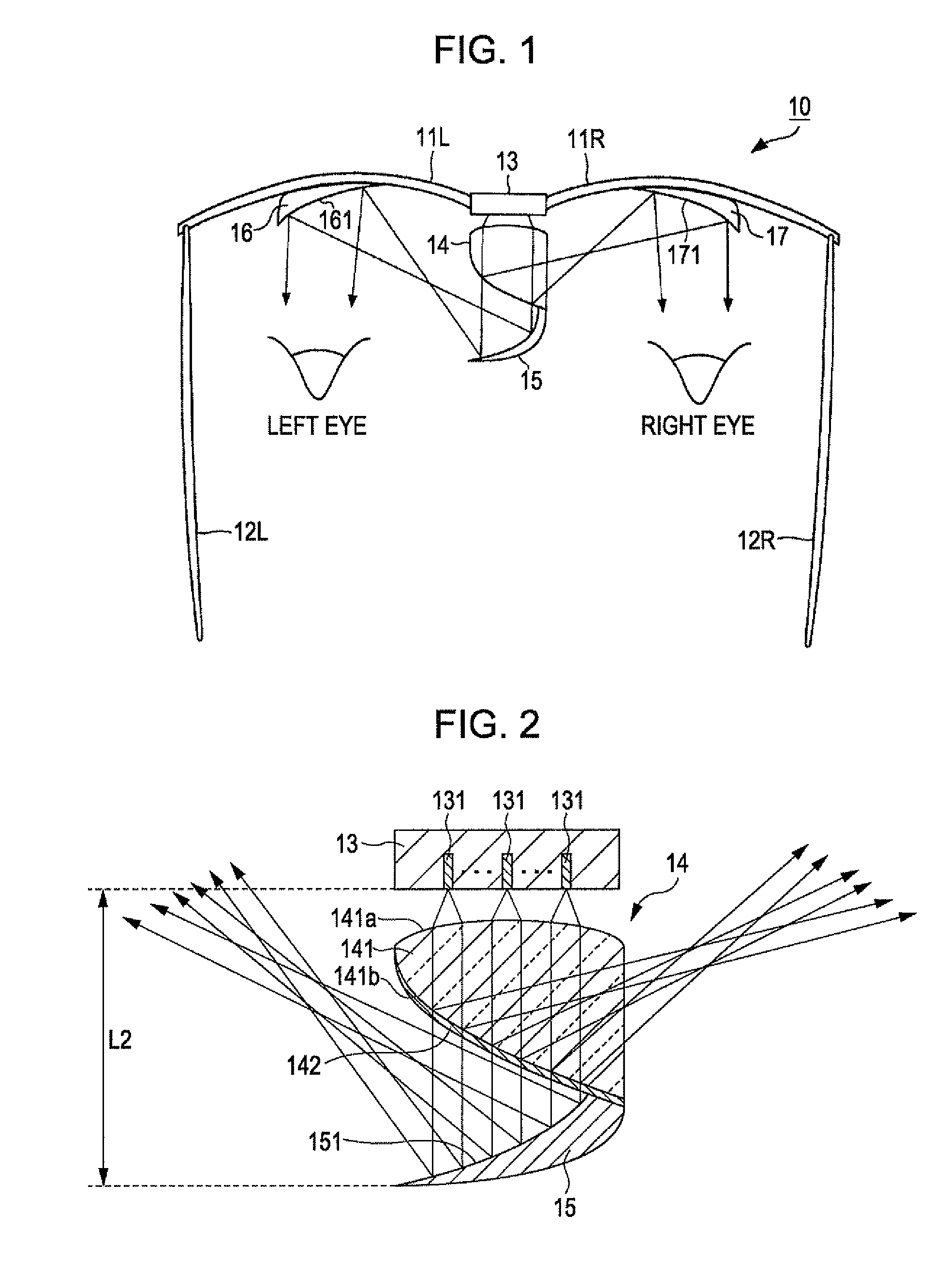
[0022]Further, the HMD 10 includes a plate-shaped display unit 13 between the lens 11L and the lens 11R. The display unit 13 outputs light to the side of the head so as to display an image. The lens 11L is attached to the left end of the display unit 13, and the lens 11R is attached to the right end of the display unit 13. Further, a nose pad ...

second embodiment

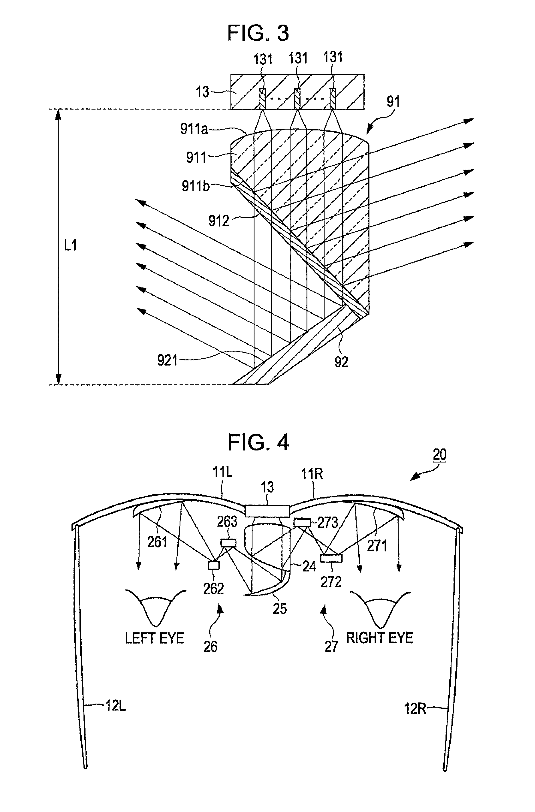
[0038]FIG. 4 is a plan view illustrating a configuration of an HMD 20 according to the second embodiment of the invention. The HMD 20 is different from the HMD 10 only in that the HMD 20 includes an optical unit 24, a concave mirror 25, a first optical system 26, and a second optical system 27 in place of the optical unit 14, the concave mirror 15, the first optical system 16, and the second optical system 17. In the embodiment, the traveling direction of reflected light from the concave mirror 25 is referred to as “first direction” and the traveling direction of reflected light from the optical unit 24 is referred to as “second direction.”

[0039]The first optical system 26 is constituted by a plurality of optical parts. That is to say, the first optical system 26 is constituted by a total reflection mirror 261, a total reflection mirror 262, and a total reflection mirror 263. The total reflection mirror 261 has a reflecting surface which is concave. The total reflection mirror 262 h...

third embodiment

[0045]FIG. 5 is a plan view illustrating a configuration of an HMD 30 according to the third embodiment of the invention. The HMD 30 is different from the HMD 20 only in that the HMD 30 includes lenses 31L and 31R, a first optical system 36, and a second optical system 37 in place of the lenses 11L and 11R, the first optical system 26, and the second optical system 27.

[0046]The lenses 11L and 11R are transparent. For example, the lenses 11L and 11R are formed with glasses. The first optical system 36 is different from the first optical system 26 only in that the first optical system 36 includes a half mirror 361 having the same shape and the same size as those of the total reflection mirror 261 in place of the total reflection mirror 261. The second optical system 37 is different from the second optical system 27 only in that the second optical system 37 includes a half mirror 371 having the same shape and the same size as those of the total reflection mirror 271 in place of the tot...


PUM


Abstract

A head mounted display includes a display unit, a concave mirror, an optical unit that is arranged between the display unit and the concave mirror, transmits a part of incident light from the display unit and reflects the other part of the incident light from the display unit, a first optical system that guides light reflected by the concave mirror to the left eye, and a second optical system that guides light reflected by the optical unit to the right eye. In the head mounted display, on the concave mirror, a right end is closer to the display unit in comparison with a left end. Further, the curvature of the concave mirror at the right end is larger than the curvature of the concave mirror at the left end.

Description

BACKGROUND[0001]1. Technical Field[0002]The present invention relates to a head mounted display to be mounted on user's head.[0003]2. Related Art[0004]An existing head mounted display (hereinafter, referred to as “HMD”) includes a display for the left eye and a display for the right eye. Therefore, it is difficult to reduce the head mounted display in size. In JP-T-2001-522477, JP-A-2001-209004, and JP-T-2007-524856, HMDs which can project an image for the right and left eyes with one display are described. Any of the HMDs described in JP-T-2001-522477 and JP-A-2001-209004 display an image for the left eye (or right eye) on an upper half of one display and an image for the right eye (or left eye) on a lower half thereof. Accordingly, in order to ensure resolution, the number of dots in the vertical direction needs to be increased. That is to say, although the number of displays is reduced, reduction of the HMD in size can barely be achieved.[0005]The HMD described in JP-T-2007-52485...

Claims


Application Information

Patent Timeline
Patent Type & Authority Applications(United States)
IPC IPC(8): G02B27/01
CPCG02B2027/0178G02B27/0172
Inventor KUBOTA, TAKEHIKO
Owner SEIKO EPSON CORP
Why Eureka
Try Eureka