

Optical light emitting device
a light-emitting device and optical technology, applied in outdoor lighting, semiconductor devices for light sources, lighting and heating apparatus, etc., can solve the problem of not only adequately utilizing the remaining ligh
- Summary
- Abstract
- Description
- Claims
- Application Information
AI Technical Summary
Benefits of technology
Problems solved by technology
Method used
Image


Examples
Embodiment Construction
[0015]Other features and advantages of the present invention will become apparent from the following description of the invention which refers to the accompanying drawings.
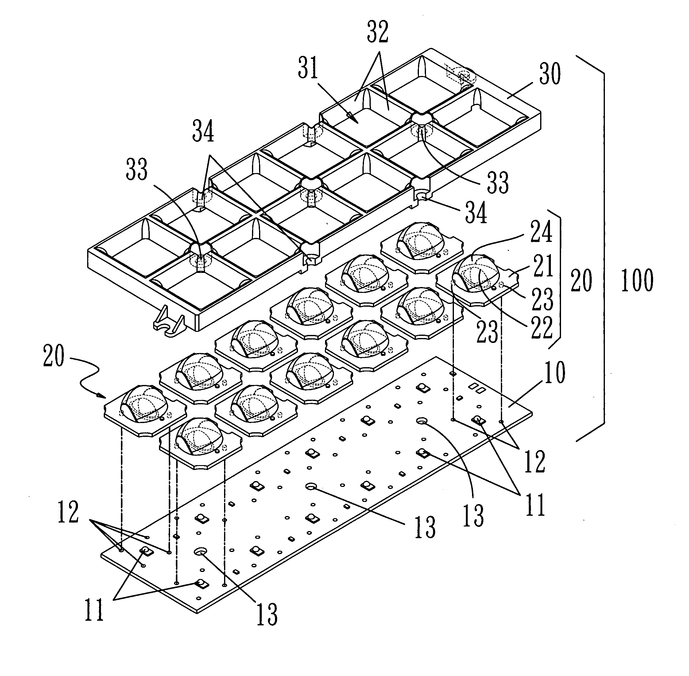
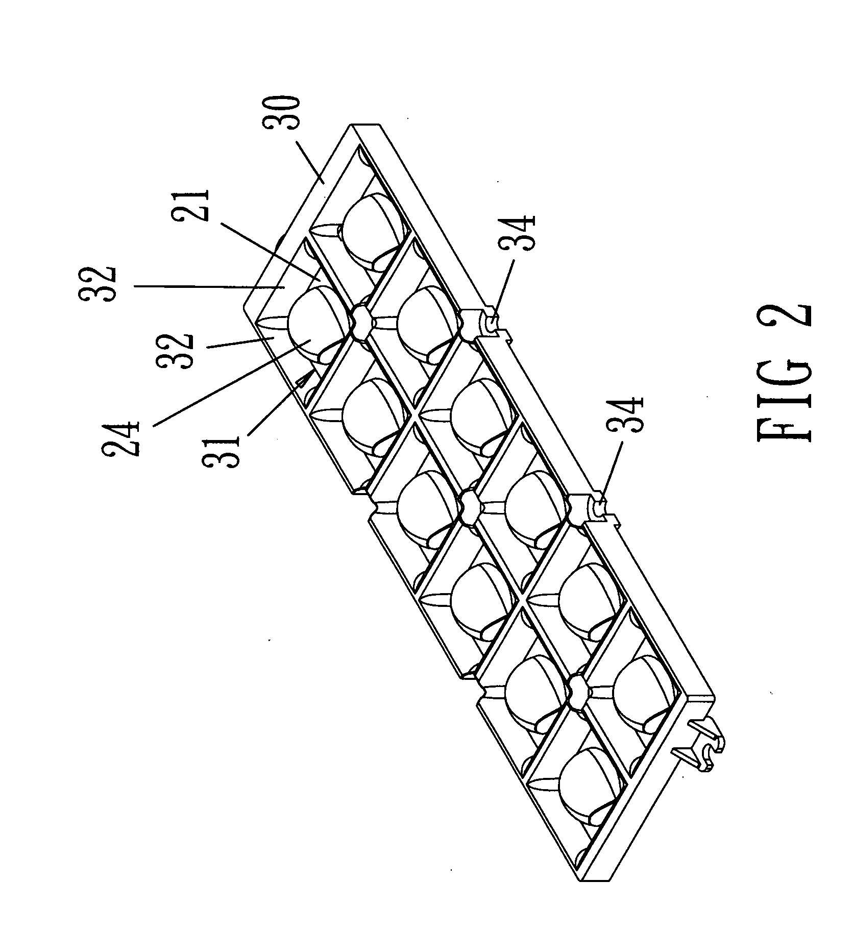
[0016]First, please refer to FIG. 1 to FIG. 4, an optical light emitting device 100 of the present invention mainly comprises a circuit substrate 10, a plurality of optical lenses 20 and a reflector 30.
[0017]The circuit substrate 10 has a plurality of LED lamps 11 arranged as an array. A proper distance is between adjacent LED lamps 11. The circuit board 10 has a plurality of positioning holes 12 disposed to an exterior periphery of each LED lamp 11. The positioning holes 12 are passed by correspondingly foot cylinders 23 of the optical lenses 20, and the circuit substrate 10 has a plurality of locking holes 13 for containing locking components 40 to install and to lock on a lamp holder 50 (as shown in FIG. 5) of a road lamp. In the embodiment, the circuit substrate 10 is designed as a rectangle plate body, wherei...
PUM
 Abstract
Description
Claims
Application Information