
Gearbox for a mixer-blender

Inactive Publication Date: 2011-12-01
VMI INC
View PDF7 Cites 2 Cited by
  • Summary
  • Abstract
  • Description
  • Claims
  • Application Information

AI Technical Summary

Benefits of technology

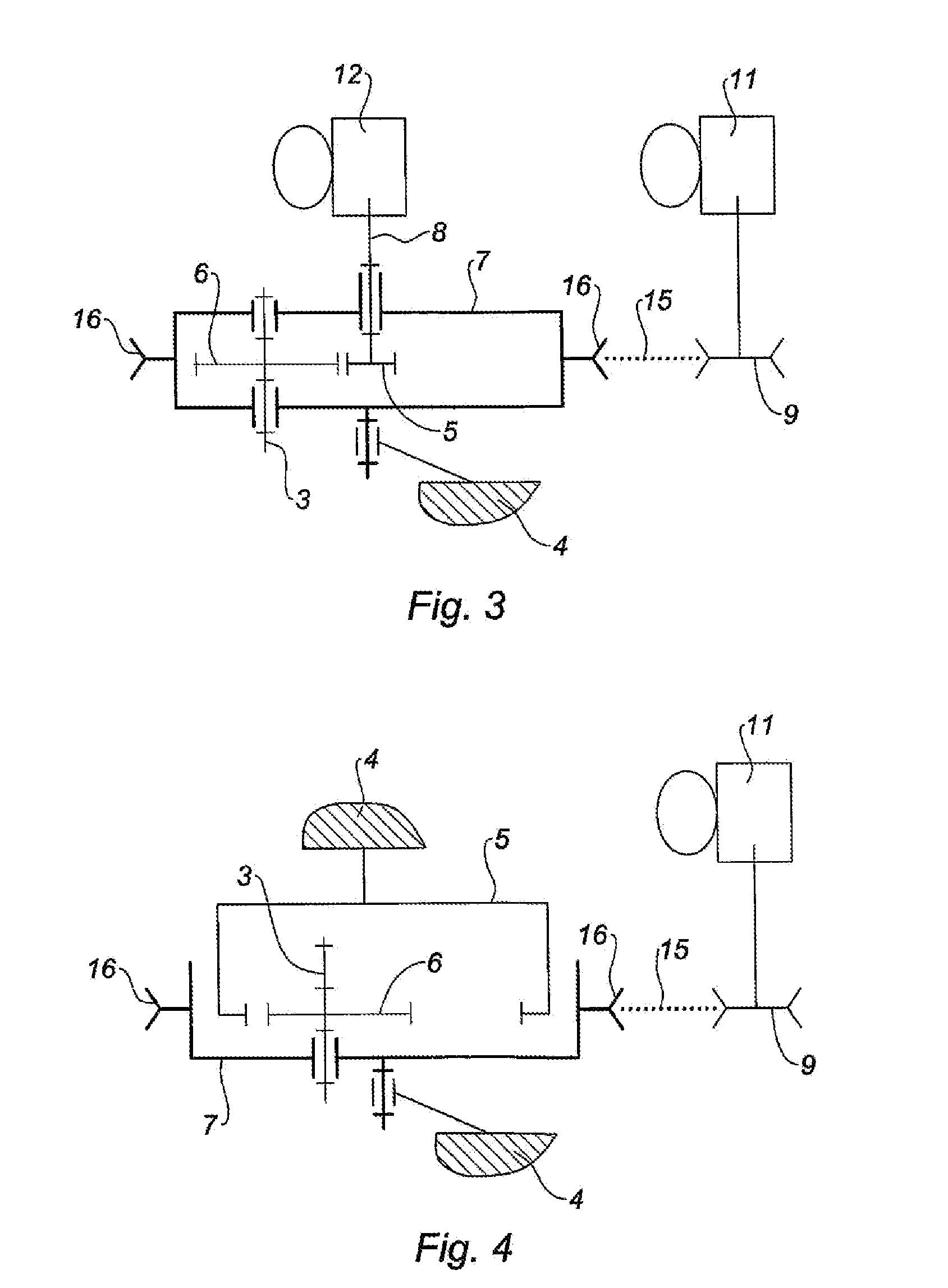
[0014]Therefore the gearbox according to the present invention is designed so that the planet carrier can be driven by a motor; this eliminates the need for the motor shaft present in the state of the art. According to the present invention, the own rotation of the planet gear is initiated directly by the rotation of the planet carrier. As a result, the elimination of the motor shaft of the planet wheel strongly reduces the need for axial space in the upper horizontal part of the stand.
[0016]According to another embodiment of the invention, the planet wheel, provided with external teeth, is mounted on a motor shaft. As in the preceding embodiment, the planet wheel allows the revolving of the planet carrier around the centre of the mixer vessel. In this configuration with two motors, the adding of a motorized planet wheel allows the transmission ratio of the gearbox to be adjusted. The axial space taken up by the motor shaft of the planet wheel is reduced, compared with a gearbox of the state of the art possibly provided with two motors.
[0017]Advantageously, the planet wheel and the planet gear are arranged inside the enclosure of the planet carrier. Therefore, the planet wheel and the planet gear are encapsulated within the body of the planet carrier such that they no longer interfere with the area for loading the matter to be mixed, thereby freeing access to cleaning of the mechanical parts.

Problems solved by technology

The major disadvantage lies in the large amount of space taken up by the gearbox in the upper horizontal part of the stand.
This arrangement of the planet wheel and planet gears, combined with the extensive axial congestion, then makes it extremely difficult to access the gearbox system for cleaning.
Finally, this axial space requirement is such that it is difficult to envisage the use of a second motor for the gearbox without accentuating the aforementioned shortcomings.
Therefore, this modularity of transmission ratios is difficult to make available with gearbox systems of the state of the art.

Method used


Image

  • Gearbox for a mixer-blender
  • Gearbox for a mixer-blender
  • Gearbox for a mixer-blender

Examples


Embodiment Construction

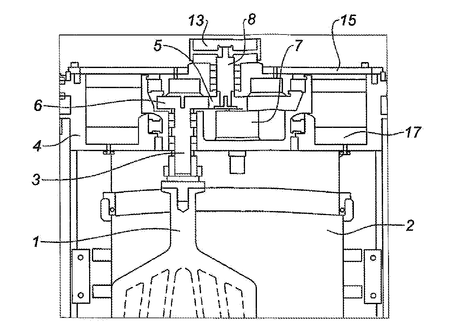
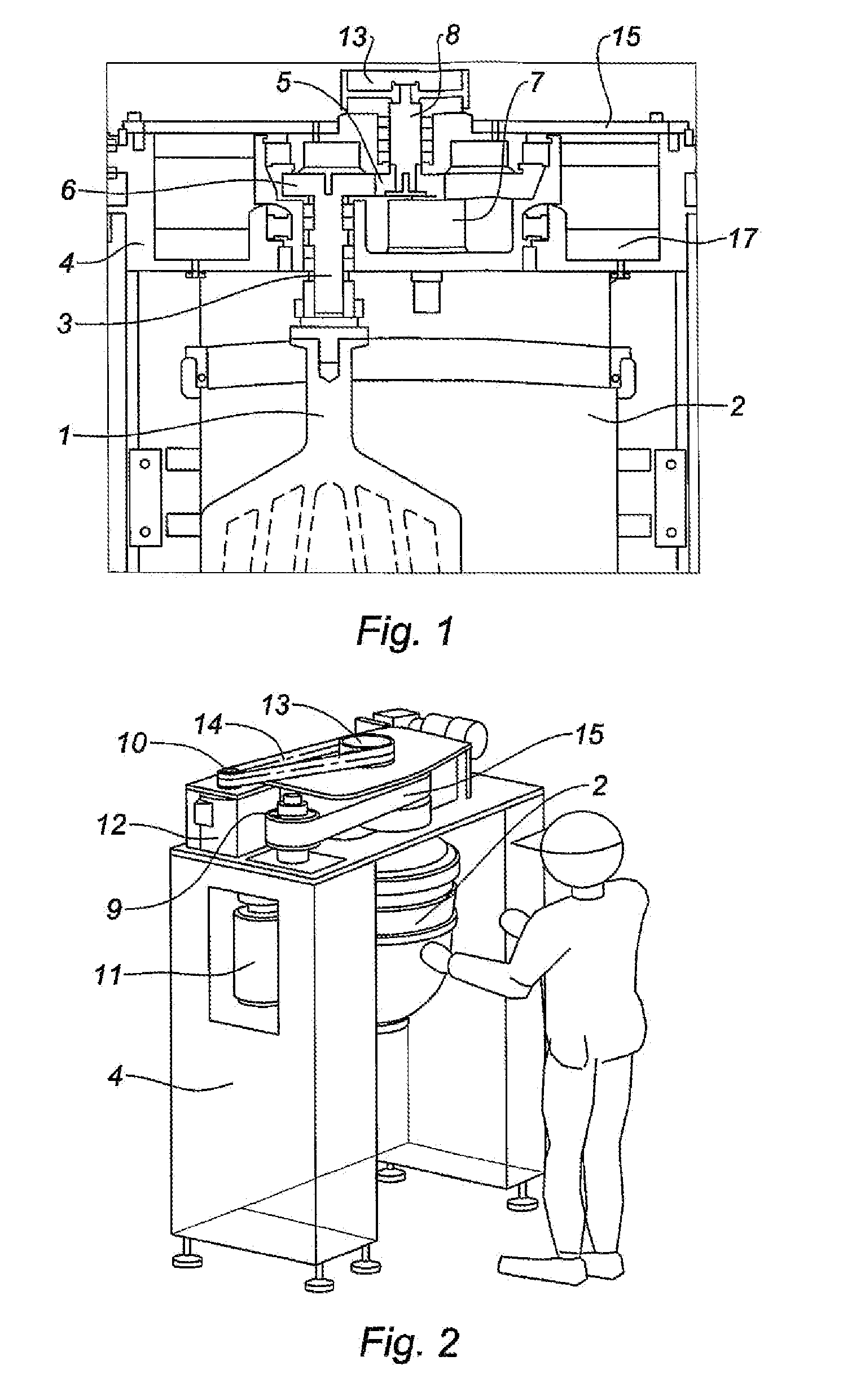
[0029]The mixer-blender illustrated in FIG. 1 comprises a mixer instrument 1 inside a mixer vessel 2. The mixer instrument is mounted on a shaft 3. The mixer vessel is arranged underneath the upper horizontal part of a stand 4.

[0030]The mixer-blender is also equipped with a gearbox comprising a planet wheel 5 and a planet gear 6. The planet wheel 5 and the planet gear 6 together form a gear system with external teeth. The planet wheel 5 and the planet gear 6 are arranged inside the enclosure of a planet carrier 7, the said planet carrier 7 forming a pulley body. The planet carrier 7 is pivot mounted on the stand 4.

[0031]The planet wheel 5 is mounted on a motor shaft 8 whilst the planet gear 6 is mounted on the shaft 3, the said shaft 3 being pivot mounted on the planet carrier 7. The motor shaft 8 is therefore kinematically linked to the shaft 3 on which the mixer instrument is mounted via the gear system with external teeth formed by the planet wheel 5 and the planet gear 6.

[0032]T...


PUM


Abstract

The present invention relates to a gearbox for a mixer-blender including a planet wheel (5), a planet carrier (7) comprising a body defining an enclosure, at least one planet gear (6) provided with external teeth and pivotably mounted on the planet carrier (7), said planet gear (6) meshing with the planet wheel (5), and characterised in that the body of the planet carrier (7) is shaped so as to engage with a driving member such that said driving member rotates the planet carrier (7).

Description

TECHNICAL FIELD[0001]The present invention relates to a gearbox intended to equip a mixer-blender.BACKGROUND[0002]Mixer-blenders are used in the food industry, in particular in the bakery and pastry trades to produce dough and creams.[0003]Mixer-blenders conventionally comprise a stand having a carrier column, an upper horizontal part and a lower part, the upper and lower parts being adjacent to the carrier column. A mixer vessel containing the matter to be mixed is then arranged between the lower part and the upper horizontal part of the stand.[0004]Mixer-blenders further comprise a motorized gearbox intended to drive at least one mixer instrument inside the mixer vessel. A gearbox for mixer-blender typically comprises a ring gear, a planet wheel and at least one planet gear. The ring gear is a pinion with inner teeth fixedly mounted on the stand.[0005]The term planet wheel designates a pinion whose axis of rotation is immobile. The term planet gear designates a pinion whose own ax...

Claims


Application Information

Patent Timeline
IPC IPC(8): F16H1/28B01F7/00
CPCB01F7/30B01F27/95
Inventor CHEIO DE OLIVEIRA, JOSEDAHERON, HENRIRICARD, PASCAL
Owner VMI INC
Learn More