Cable assembly with elecrical and optical transmitting

a cable and optical transmission technology, applied in the direction of optical elements, coupling device connections, instruments, etc., can solve the problems of increasing the total dimension of the cable assembly, limiting the transmission speed of electrical signals, and complex assembly

Inactive Publication Date: 2011-12-01
HON HAI PRECISION IND CO LTD
View PDF5 Cites 50 Cited by
  • Summary
  • Abstract
  • Description
  • Claims
  • Application Information

AI Technical Summary

Problems solved by technology

However, transmitting speed is limited via electrical signal transmitting.
In other aspect, as transmitting speed increasing, a structure of the cable assembly becomes complex, and a total dimension of the cable assembly is increasing.

Method used


Image

  • Cable assembly with elecrical and optical transmitting
  • Cable assembly with elecrical and optical transmitting
  • Cable assembly with elecrical and optical transmitting

Examples


Embodiment Construction

[0016]Reference will now be made in detail to the preferred embodiment of the present invention.

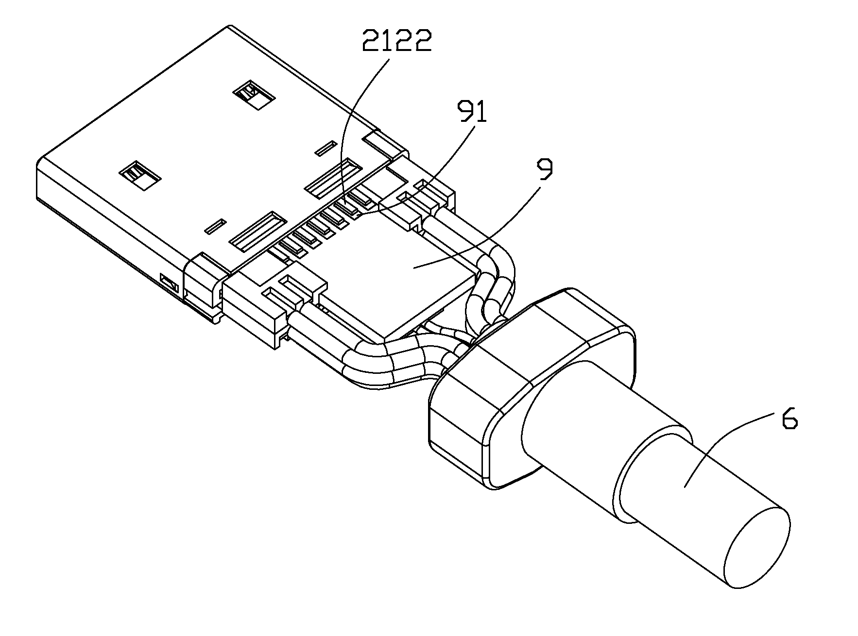
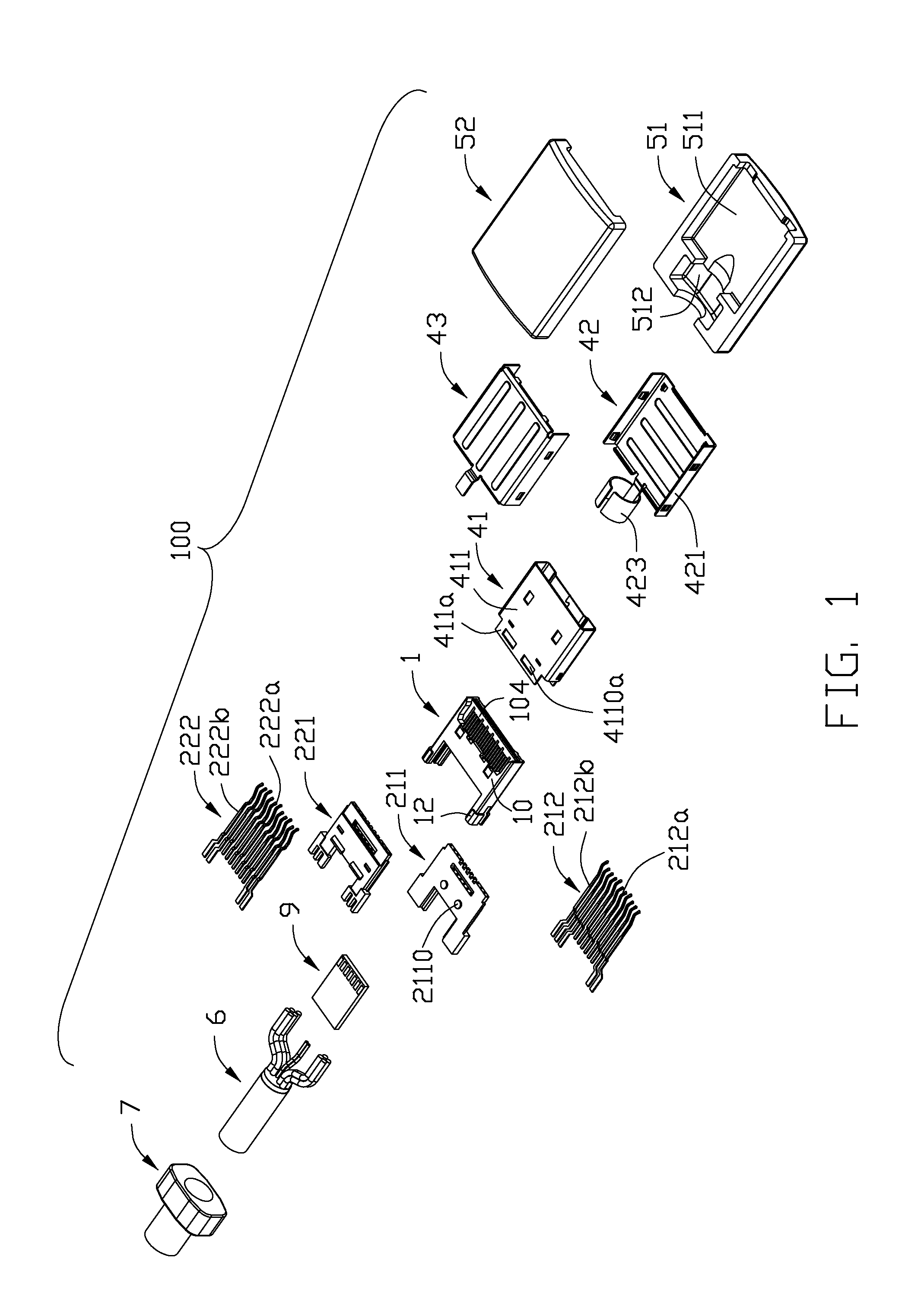
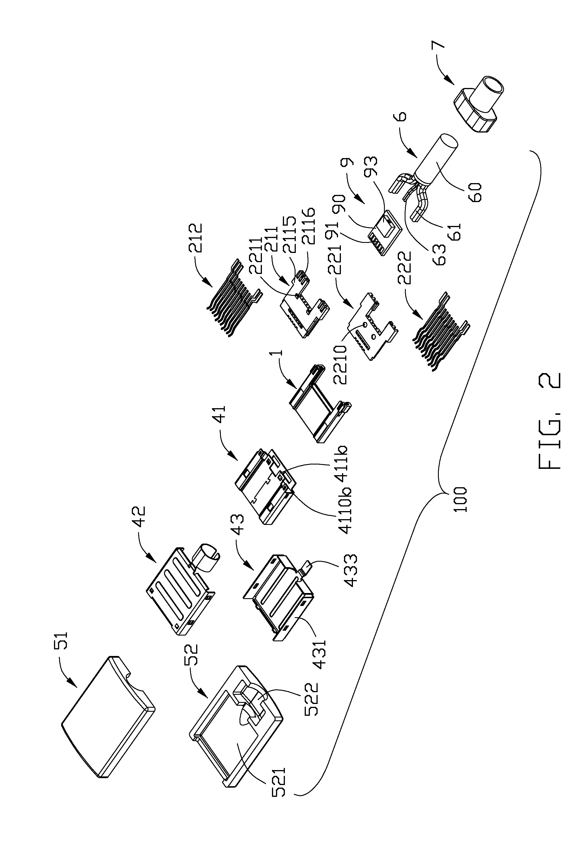
[0017]Referring to FIGS. 1-8, a cable assembly 100 in accordance with the present invention comprises an insulative housing 1, a terminal module 2, a metallic shell 4, an external cover 5, a cable 6, a strain relief 7 integrally formed with a front section of the cable 6 and a printed circuit board assembly (PCBA) 9.

[0018]The insulative housing 1 includes a flat main portion 10 and two mounting arms 12 extending rearwardly from lateral sides of the main portion 10. A mounting recess 102 is recessed forwardly from a middle segment of a rear edge of the main portion 10. A mating cavity 104 is recessed downwardly from a front segment of an upper side of the main portion 10 and further communicates with the mounting recess 102. A depression 105 is defined in a front section of a lower side of the main portion 10. There is a receiving spacer 121 disposed between the two mounting arms 12.

[0019]...


PUM


Abstract

An cable assembly (100) includes an insulative housing (1); a first terminal module (21) and a second terminal module (22) assembled to the insulative housing, the first terminal module (21) having first terminals (212a) and first additional terminals (212b), the second terminal module (22) having second terminals (222a) and second additional terminals (222b); a photoelectric conversion device (93) electrically connected with the first terminals and the second terminals; and a cable (6) including fiber wires (63) and copper wires (61), the fiber wires optically connected to photoelectric conversion device, the copper wires electrically connected to the first additional terminals and the second additional terminals.

Description

FIELD OF THE INVENTION[0001]The present invention generally relates to a cable assembly, and more particularly to a cable assembly adapted for electrical and optical transmitting.DESCRIPTION OF PRIOR ART[0002]Nowadays, an electrical device has become lower profile and multi-functional, and a cable assembly for the electrical device is required lower profile and capable of high-speed transmitting.[0003]Cable assemblies in accordance with USB, SATA, HDMI, SAS and Displayport protocol have been widely applied in different kinds of electronic devices. The aforementioned cable assemblies depend on metallic terminals and copper wires to achieve electrical signal transmitting. However, transmitting speed is limited via electrical signal transmitting. In other aspect, as transmitting speed increasing, a structure of the cable assembly becomes complex, and a total dimension of the cable assembly is increasing.[0004]Hence, an improved cable assembly is highly desired to overcome the aforement...

Claims


Application Information

Patent Timeline
Patent Type & Authority Applications(United States)
IPC IPC(8): G02B6/44H02G3/00
CPCG02B6/3817H01R4/30H01R13/6658H01R13/6594H01R2107/00H01R13/6471H01R13/6593H01R24/60
Inventor WU, JERRY
Owner HON HAI PRECISION IND CO LTD
Why Eureka
Try Eureka