Two piece roof vent

a roof vent and two-piece technology, applied in ventilation systems, heating types, lighting and heating apparatus, etc., can solve the problems of inability to easily form injection molding and relatively bulky roof vents, and achieve the effect of convenient manufacturing

Inactive Publication Date: 2011-12-01
ALPHA SYST
View PDF8 Cites 53 Cited by
  • Summary
  • Abstract
  • Description
  • Claims
  • Application Information

AI Technical Summary

Benefits of technology

[0003]The present invention is premised on the realization that a more compact, easily manufactured roof vent can be formed in two sections, an inner section and an outer section, both sect...

Problems solved by technology

This construction causes the roof vents to be relatively b...

Method used


Image

  • Two piece roof vent
  • Two piece roof vent
  • Two piece roof vent

Examples


Embodiment Construction

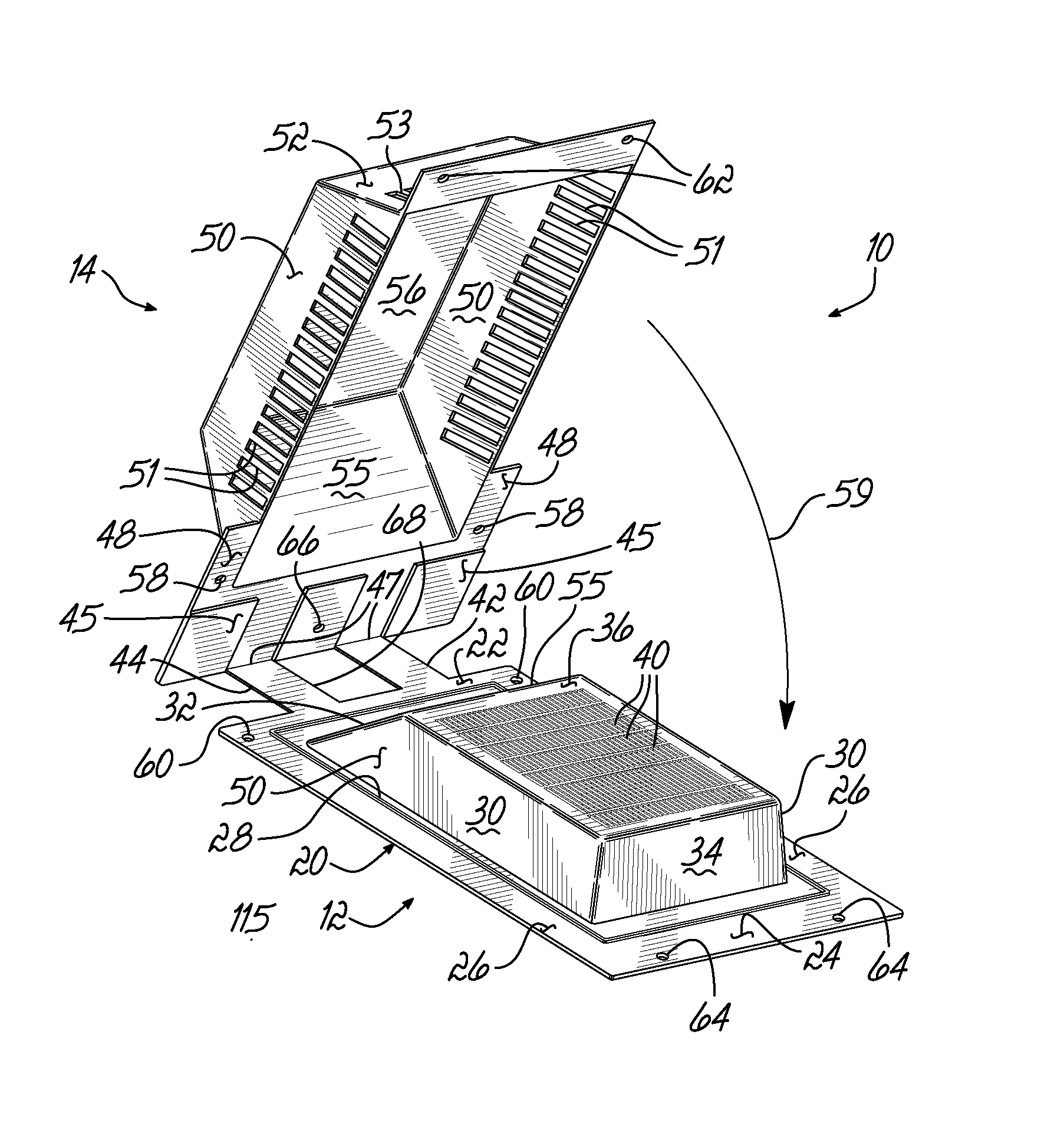
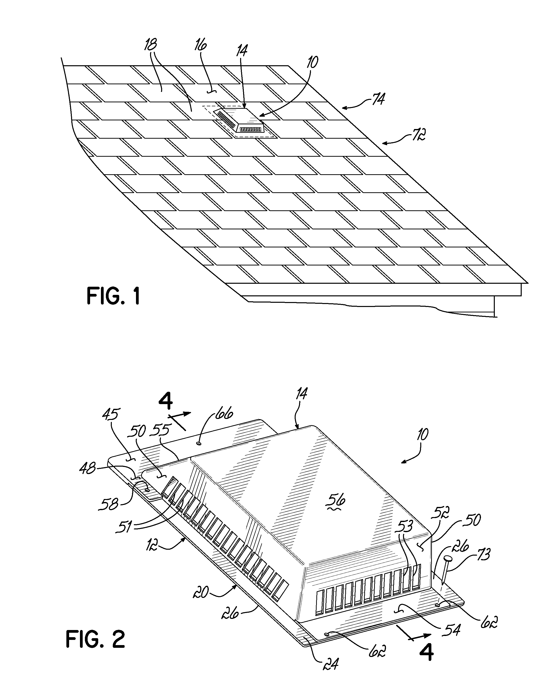
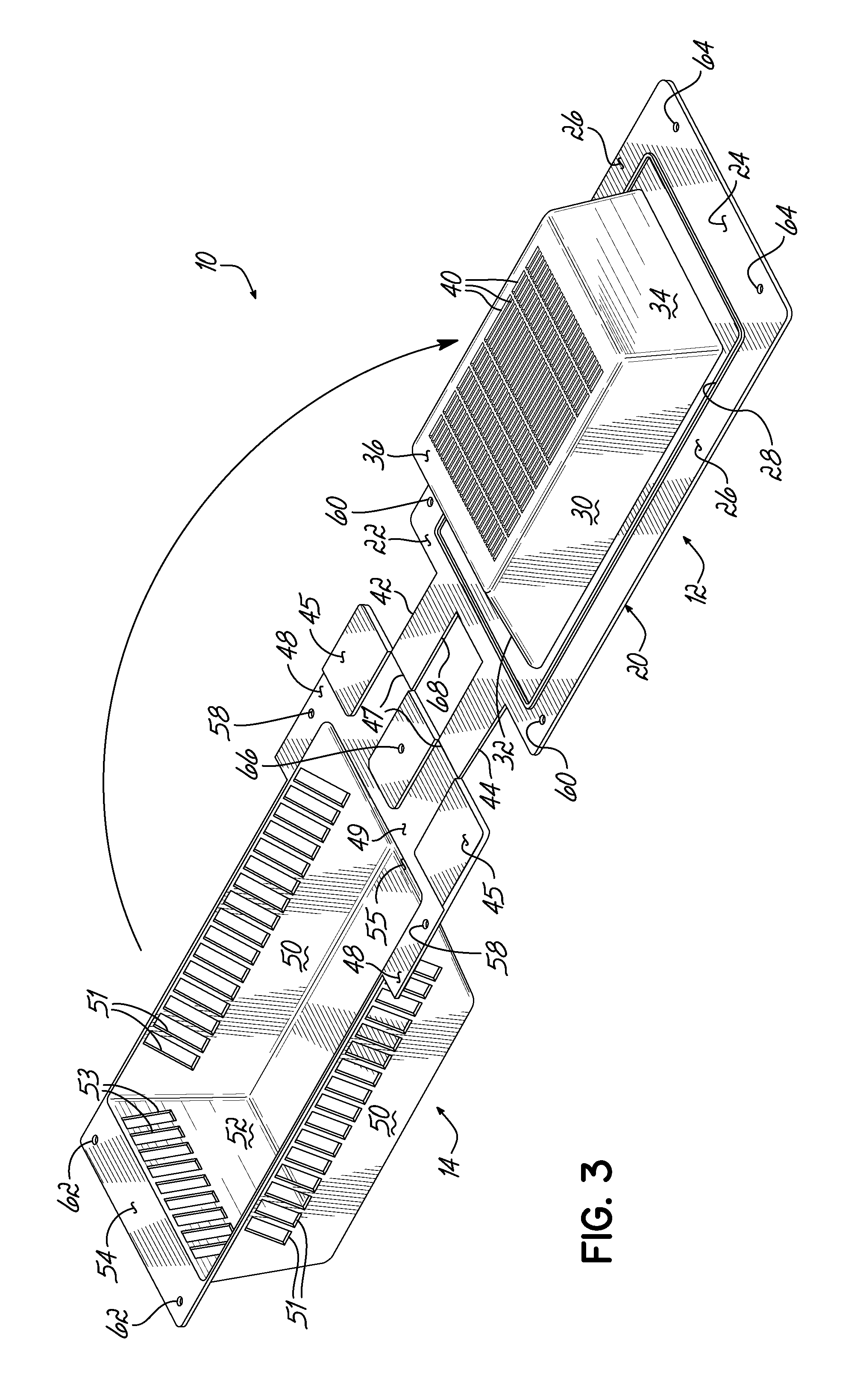
[0013]According to the present invention, a roof vent 10 includes an inner base member 12 and an outer cover member 14. The vent 10 is attached to a roof surface 16 and covers an opening 17 through the roof surface 16. The roof vent 10, in turn, is surrounded by shingles 18. The vent can be plastic and formed by injection molding or the vent can be metal.

[0014]The base member 12 has a peripheral flange 20 formed from a top flange 22, a bottom flange 24 and two side flanges 26. Peripheral flange 20 includes a circumferential raised shoulder 28. Sloped side walls 30, forward wall 32, and back wall, or lower wall 34 extend up from shoulder portion 28 and surround a top wall 36. The base member 12 includes upper air openings 38 through wall 32, and air openings 40 through top wall 36. These openings are relatively small to keep bugs from passing through the vent. The remaining side walls 30 and lower wall 34 are solid to prevent water ingress.

[0015]As shown in the one piece embodiment o...


PUM


Abstract

A roof vent designed to be nestable for easy shipment and which can be injection molded includes a base member and cover member. The base is nestable in an identical base, and the cover is nestable in an identical cover. The base and cover can be totally separate or connected by a living hinge or runner. To install the vent, the cover is positioned over the base and the two are nailed together to the roof surface.

Description

BACKGROUND OF THE INVENTION[0001]Generally, roof vents on residential buildings are nailed to the roof surface and cover a hole which extends through the roof surface into an attic space. The vents are attached to the roof at the same time the roof is shingled, with the bottom flange of the roof vent extending over a lower row of shingles, and an upper row of shingles extending over a top flange of the roof vent. The roof vent has an inner section and an outer section that creates a circuitous path preventing water from passing through the outer openings in the roof vent into the building but allow air through the vent.[0002]This construction causes the roof vents to be relatively bulky. If several vents are shipped together, they are usually in individual packages because these vents do not nest. Further, they cannot be easily formed by injection molding.SUMMARY OF THE INVENTION[0003]The present invention is premised on the realization that a more compact, easily manufactured roof ...

Claims


Application Information

Patent Timeline
IPC IPC(8): F24F7/02F24F13/20
CPCF24F7/02
Inventor VAGEDES, MICHAEL
Owner ALPHA SYST
Why Eureka
Try Eureka