Post card

Inactive Publication Date: 2011-12-01
HONG FU JIN PRECISION IND (SHENZHEN) CO LTD +1
View PDF5 Cites 8 Cited by
  • Summary
  • Abstract
  • Description
  • Claims
  • Application Information

AI Technical Summary

Problems solved by technology

Current POST cards typically have only one connector and thus can only connect to computer motherboards that include an interface matching the connector.
For example, a POST card on

Method used


Image

  • Post card
  • Post card
  • Post card

Examples


Embodiment Construction

[0009]Embodiments of the present POST card will now be described in detail with reference to the drawings.

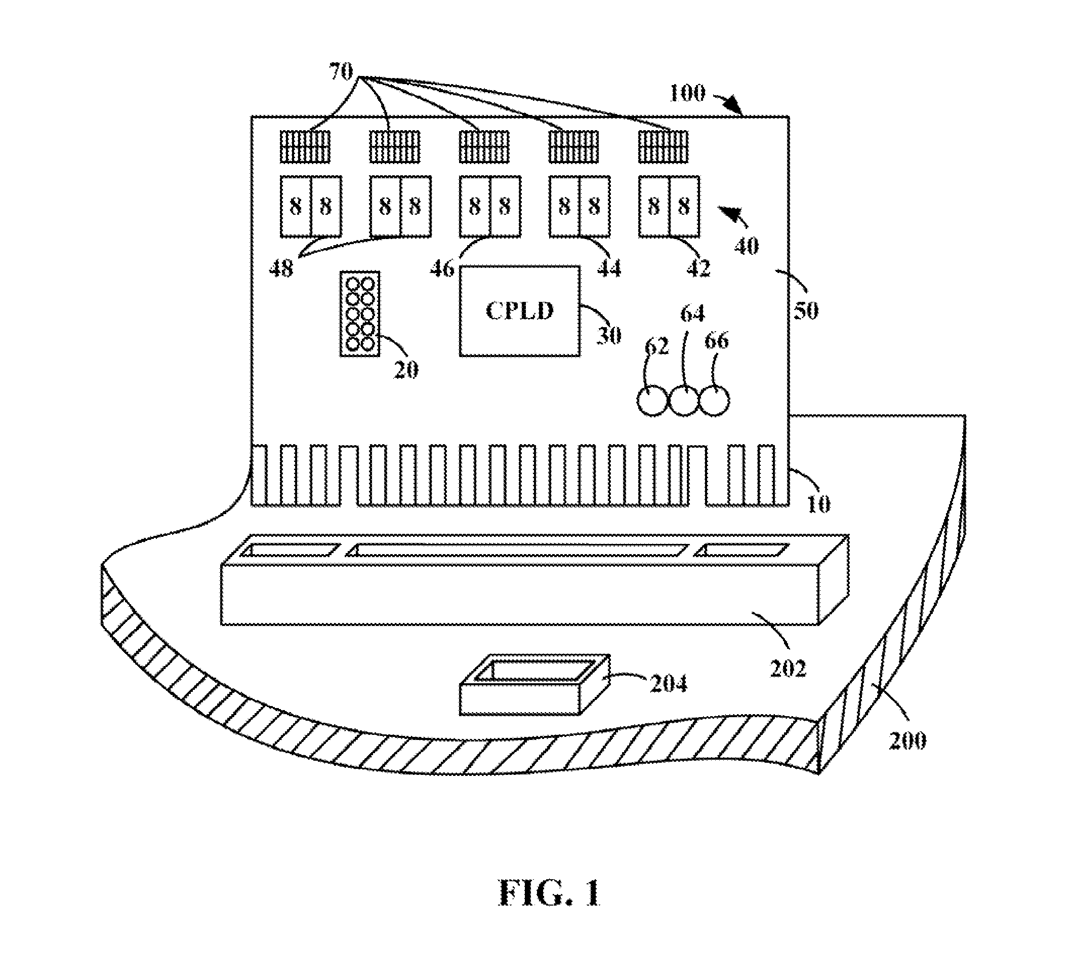
[0010]Referring to FIG. 1, a POST card 100, according to an embodiment, includes a PCI connector 10, a low pin count (LPC) connector 20, a controller 30, an indicating module 40, a printed circuit board (PCB) 50, three light emitting diodes (LEDs) 62, 64, and 66, and a set of Boolean switches 70.

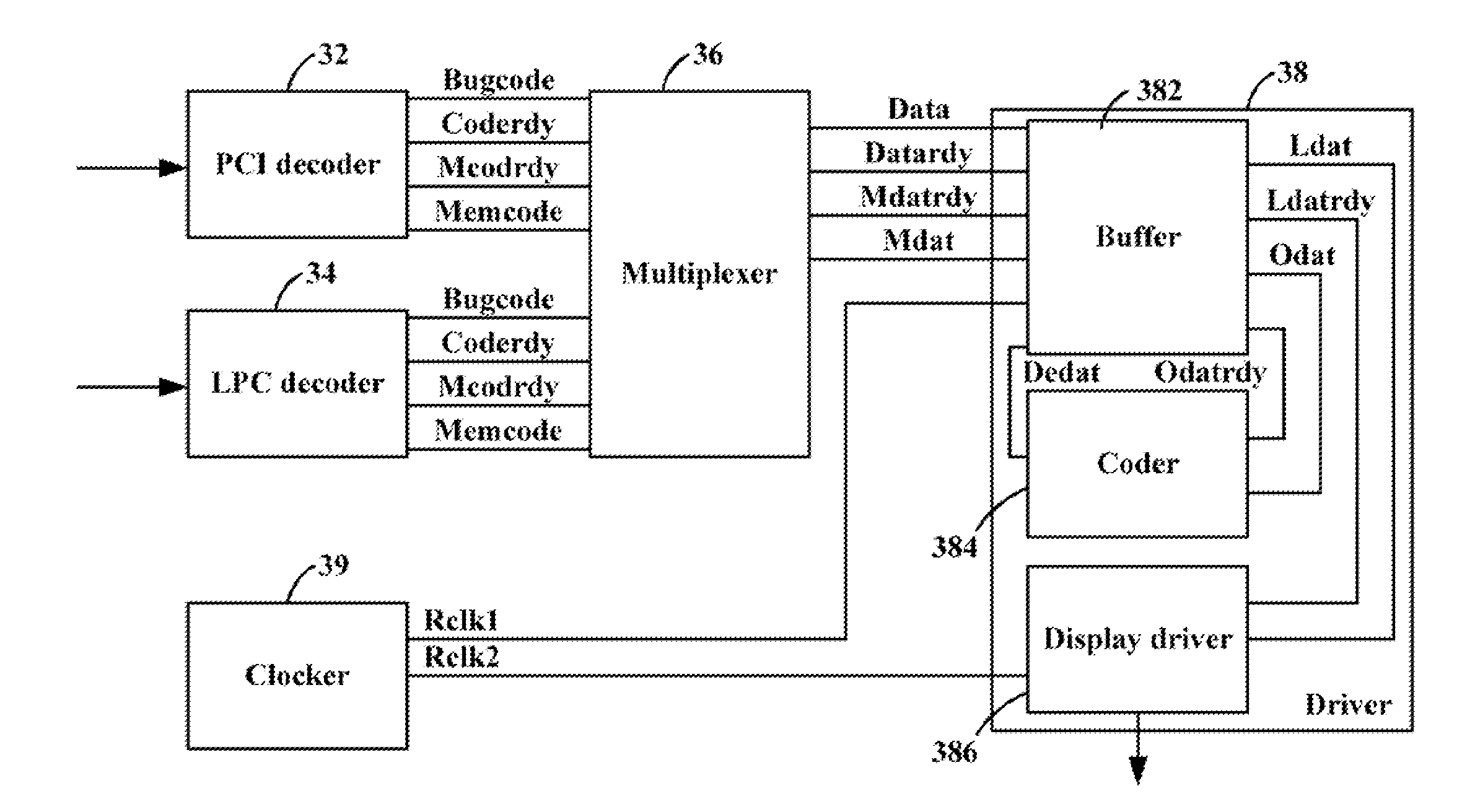
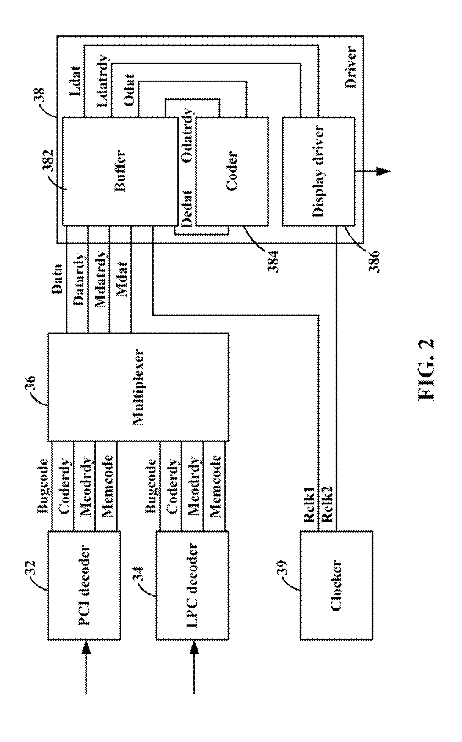
[0011]The PCI connector 10 is configured for connecting the POST board 100 to a computer motherboard (not shown) to be diagnosed thereby having a PCI interface (not shown) to read error codes generated by the computer motherboard. The LPC connector 20 is configured for connecting the POST board 100 to a computer motherboard (not shown) to be diagnosed thereby having an LPC interface (not shown) to read error codes generated by the computer motherboard. The controller 30 is configured for controlling the indicating module 40 to indicate the error codes from the PCI connector 10 or the LPC...


PUM


Abstract

A POST card includes a PCI connector, an LPC connector, a controller, and an indicating module. The controller includes a PCI decoder, an LPC decoder, a multiplexer, and a driver. The POST card connects to and reads error codes from a computer motherboard by the PCI connector or the LPC connector depending on which type of interface the computer motherboard has. The PCI decoder is activated and decodes the error codes read through the PCI connector. The LPC decoder is activated and decodes the error codes read through the LPC connector. The multiplexer connects the driver to the PCI decoder or the LPC decoder to transmit the error code to the driver depending on which one of the PCI connector and the LPC connector is connected to the computer motherboard. The driver drives the indicating module to display the error codes.

Description

BACKGROUND[0001]1. Technical Field[0002]The present disclosure relates to a post-on self-test (POST) card.[0003]2. Description of Related Art[0004]Current POST cards typically have only one connector and thus can only connect to computer motherboards that include an interface matching the connector. For example, a POST card only having a peripheral component interconnect (PCI) connector can only connect to computer motherboards having a PCI interface and is not available for other computer motherboards.[0005]Therefore, it is desirable to provide a POST card which can overcome the above-mentioned limitations.BRIEF DESCRIPTION OF THE DRAWINGS[0006]Many aspects of the present POST card should be better understood with reference to the following drawings. The components in the drawings are not necessarily drawn to scale, the emphasis instead being placed upon clearly illustrating the principles of the present POST card. Moreover, in the drawings, like reference numerals designate corres...

Claims


Application Information

Patent Timeline
IPC IPC(8): G06F11/07G06F15/177
CPCG06F11/2284
Inventor CAO, ZHAO-JIE
Owner HONG FU JIN PRECISION IND (SHENZHEN) CO LTD
Why Eureka
Try Eureka