Welding control

Active Publication Date: 2011-12-08
ESAB AB
View PDF8 Cites 4 Cited by
  • Summary
  • Abstract
  • Description
  • Claims
  • Application Information

AI Technical Summary

Benefits of technology

[0007]The object of the present invention is therefore to alleviate the above problems and offer a robust, flexible and cost efficient solution for automatic application of weld material in narrow joints.
[0013]According to yet another preferred embodiment of the invention, either as an alternative or a complement to the above, the welding head is configured to be tilted around a tilt axis that is essentially parallel to the operating direction. Consequently, the welding action can be conveniently aimed at different areas inside the joint.
[0014]According to a further preferred embodiment of the invention, the welding device includes a powder channel configured apply welding powder in the spacing between the work pieces. The powder channel has an outlet, which is arranged upstream of the welding head and downstream of the primary sensor members relative to the operating direction during transport of the device along this direction. Thus, an adequate amount of powder can be applied without risking interfering with the measurement of joint profile's geometric properties.
[0015]According to another preferred embodiment of this aspect of the invention, the welding head is configured to administer at least one consumable electrode wire into the spacing between the work pieces. Additionally, it is preferable if the welding head has at least two wire outputs, which are configured to feed out a respective electrode. Moreover, the outputs are arranged such that a stick-out of a first electrode is angled relative to a stick-out of a second electrode. Consequently, the welding process can be made very efficient. It is also rendered possible to further adapt the welding to the properties of the joint.
[0016]Generally, the invention is beneficial because it enables high-precision welding in narrow joints with steep edges. The solution is therefore well suited for welding of reactor tanks and other demanding junctions of thick metal plates.

Problems solved by technology

However, due to the design, the arrangement is limited to be applied in joint profiles where the joint edges deviate considerably from being fully vertical surfaces.
For example, the arrangement cannot be used in joints where the edges constitute essentially parallel surfaces.
Particularly, it is impossible to use the arrangement for welding comparatively thick work pieces with narrow joints having steep edges.

Method used


Image

  • Welding control
  • Welding control
  • Welding control

Examples


Embodiment Construction

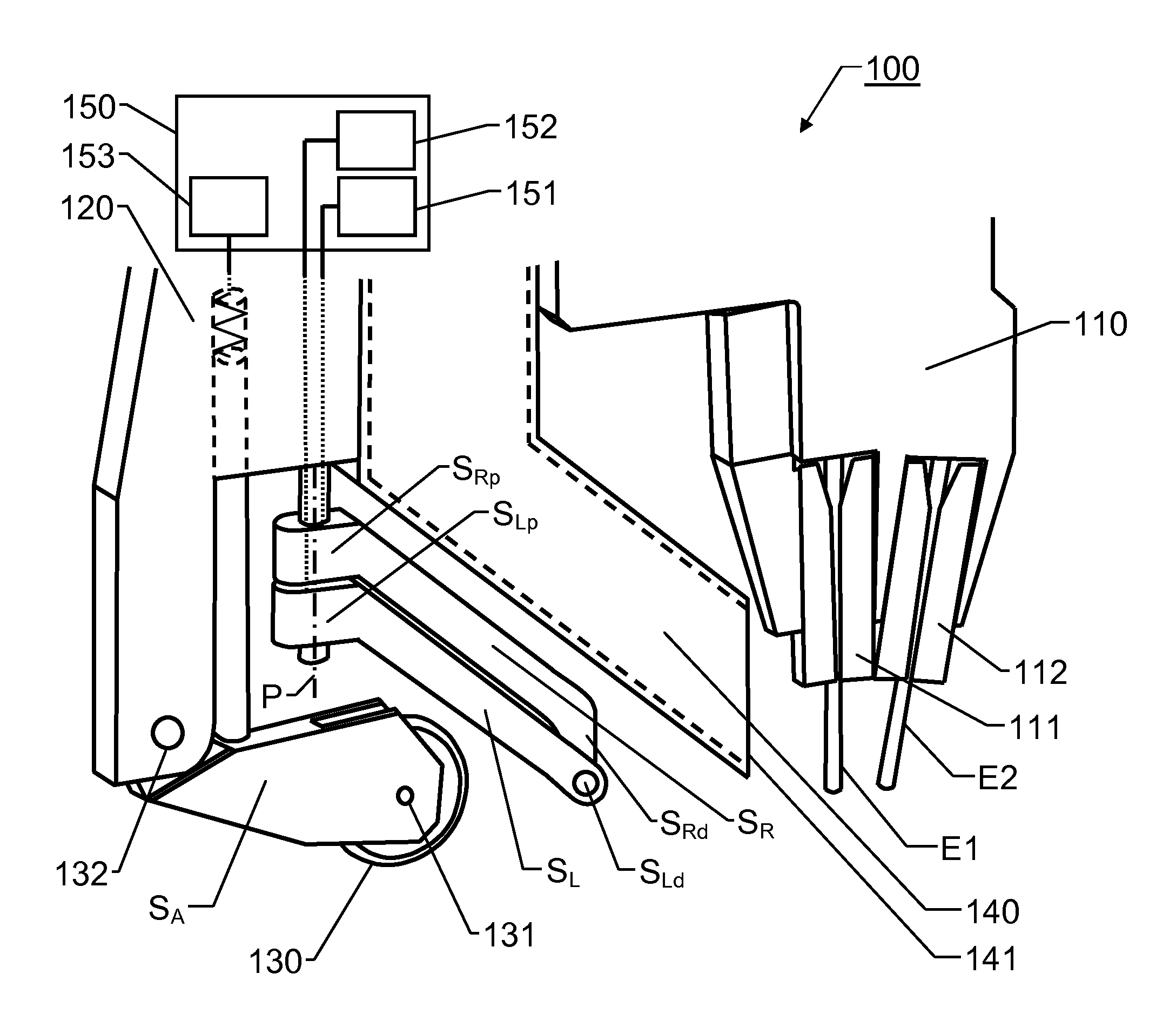
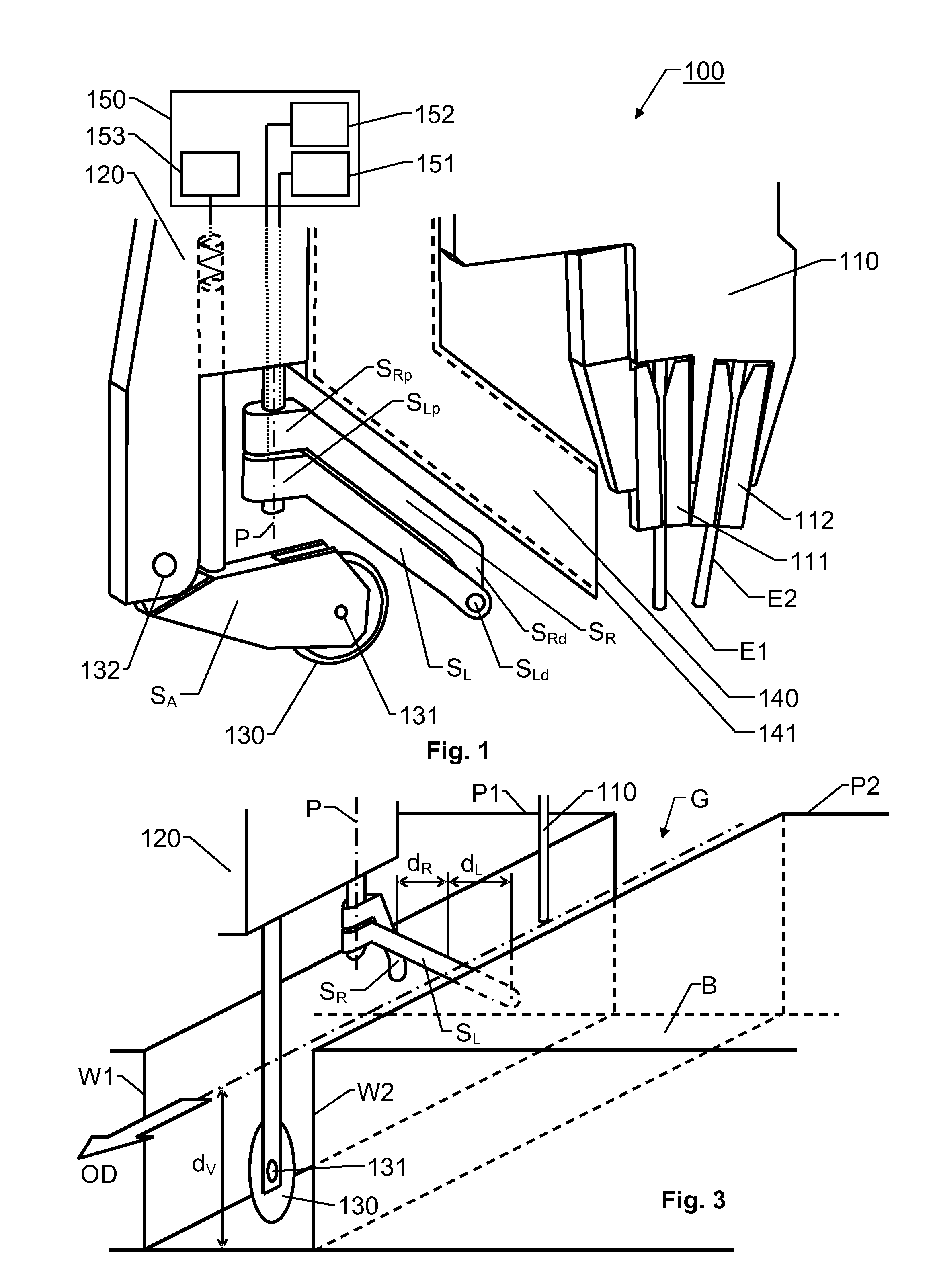
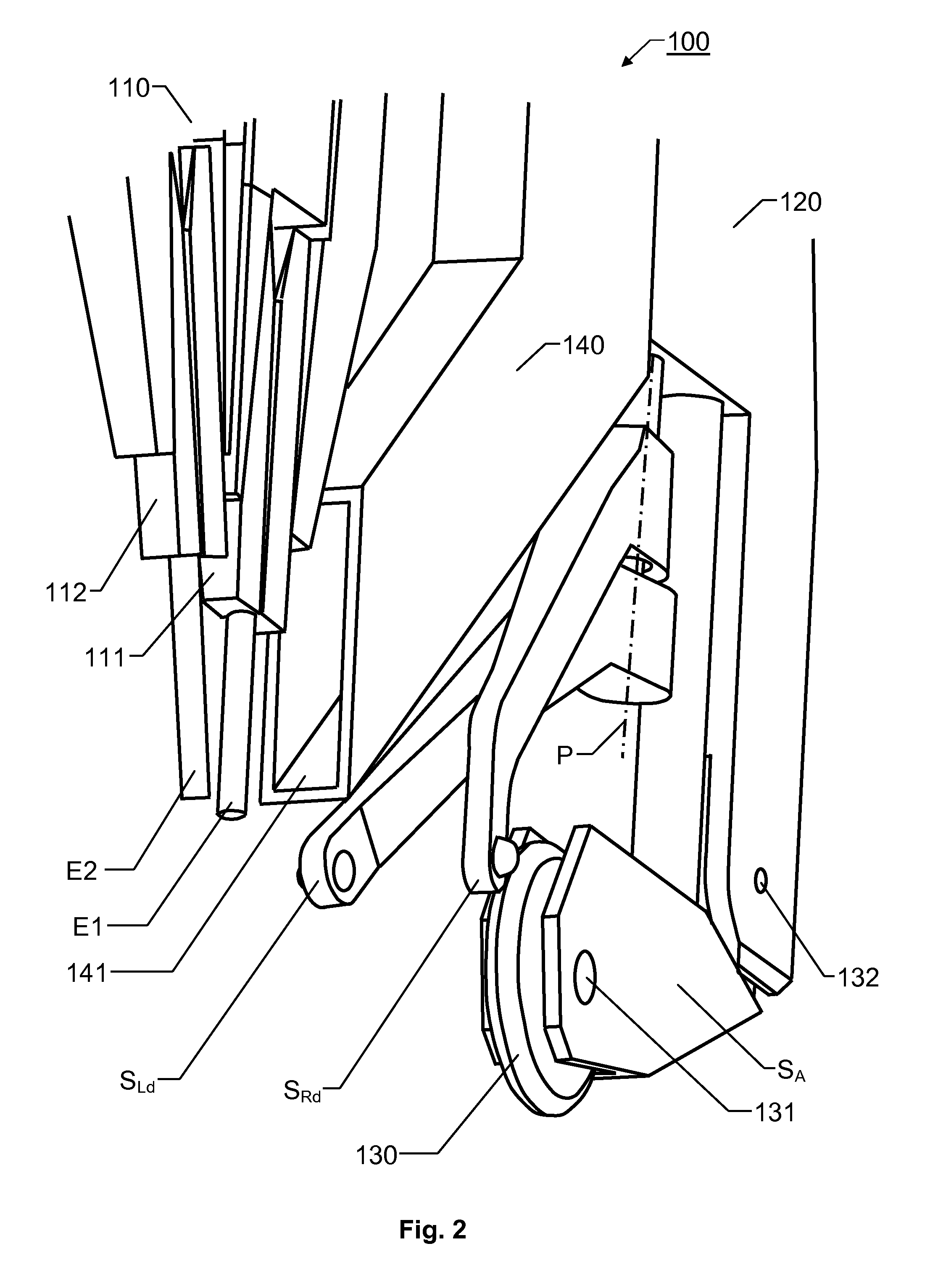
[0027]We refer initially to FIG. 1, which shows a welding device 100 according to one embodiment of the invention. FIG. 2 shows the welding device 100 of FIG. 1, however from a somewhat different perspective.

[0028]The device 100 is adapted to apply weld material between two work pieces so as to connect these pieces mechanically with one another. The proposed device 100 includes a welding head 110 and a central element 120. According to embodiments of the invention, the device 100 may also include an auxiliary sensor means SA and / or a powder channel 140. The device 100 may further include a measurement unit 150 for registering and processing measurement data.

[0029]The welding head 110 is configured to perform a welding action in respect of the work pieces during transport of the device 100 along an operating direction. The central element 120 includes two primary sensor members SR and SL respectively, which are arranged upstream of the welding head 110 relative to the operating direc...


PUM

PropertyMeasurementUnit
Distanceaaaaaaaaaa

Abstract

A welding device applies weld material between two work pieces such that the work pieces are connected mechanically with one another. The welding device includes a welding head and a central element. The welding head performs a welding action during transport thereof along an operating direction between the work pieces. Two primary sensor members are arranged on the central element upstream of the welding head relative to the operating direction. The sensor members register geometric properties of a spacing between the work pieces in which spacing the weld material is to be applied. Each sensor member is configured to maintain contact with a respective wall of the two work pieces adjoining the spacing while allowing variation of lateral distances between the central element and the adjoining wall. This is accomplished by the sensor members being pivotally attached to the central element via at least one pivoting axis oriented essentially perpendicular to the operating direction.

Description

THE BACKGROUND OF THE INVENTION AND PRIOR ART[0001]The present invention relates generally to precision welding. More particularly the invention relates to a welding device according to the preamble of claim 1.[0002]Technical solutions for automatic welding have been known for decades. Below follows some examples of how a welding device can be controlled to apply welding material between two work pieces so as to connect these mechanically with one another.[0003]EP 423 088 discloses a method for automatic multi-run welding of butt joints. Here, a sensor having a feeler rod with a ball-shaped tip oscillates transverse to the weld joint to scan the joint at several portions. Thus, the sensor determines a contour of the joint, and the welding can be adapted accordingly as the welding device progresses through the joint.[0004]JP 59209483 describes a solution for detecting a groove width and in response thereto controlling a welding process. A pair of stylus sensors slides orthogonally ac...

Claims


Application Information

Patent Timeline
IPC IPC(8): B23K9/28B23K37/00
CPCB23K9/1278B23K9/0216B23K9/02B23K9/127
Inventor MELIN, BOOSTERGREN, PERLARSSON, HAKANJANSSON, BOJANSSON, LARS E.
Owner ESAB AB
Why Eureka
Try Eureka