
Dual function door for an aircraft engine nacelle

Active Publication Date: 2011-12-08
AIRBUS OPERATIONS (SAS) +1
View PDF4 Cites 30 Cited by
  • Summary
  • Abstract
  • Description
  • Claims
  • Application Information

AI Technical Summary

Benefits of technology

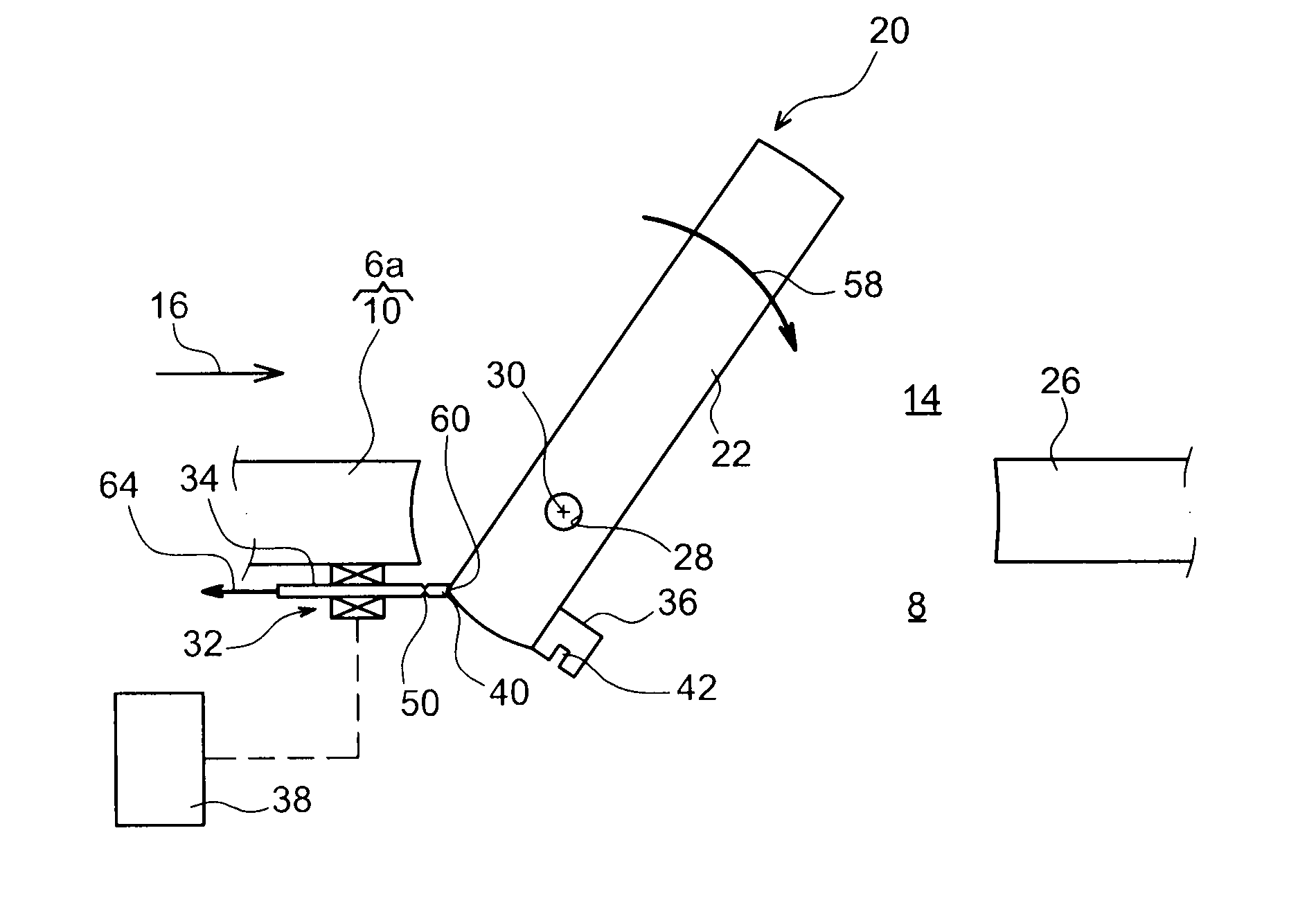
[0014]Preferably, the door is designed so that the opening leaf may be moved from the open position to the closed position under the effect of a closing gas pressure which is applied on the opening leaf. This closing gas pressure may in particular be applied by the secondary flow of the engine, when the latter assumes the form of a ducted-fan jet turbine engine. Alternatively, closing of the opening leaf may be performed with conventional controlled means, for example those also being used for ensuring the opening of the opening leaf. The retained preferential solution nevertheless has the advantage of getting rid of risks of failure of the control means, since the closing is carried out by having a gas flow simply pass over the outer surface of the opening leaf, leading to the shutting of the latter.
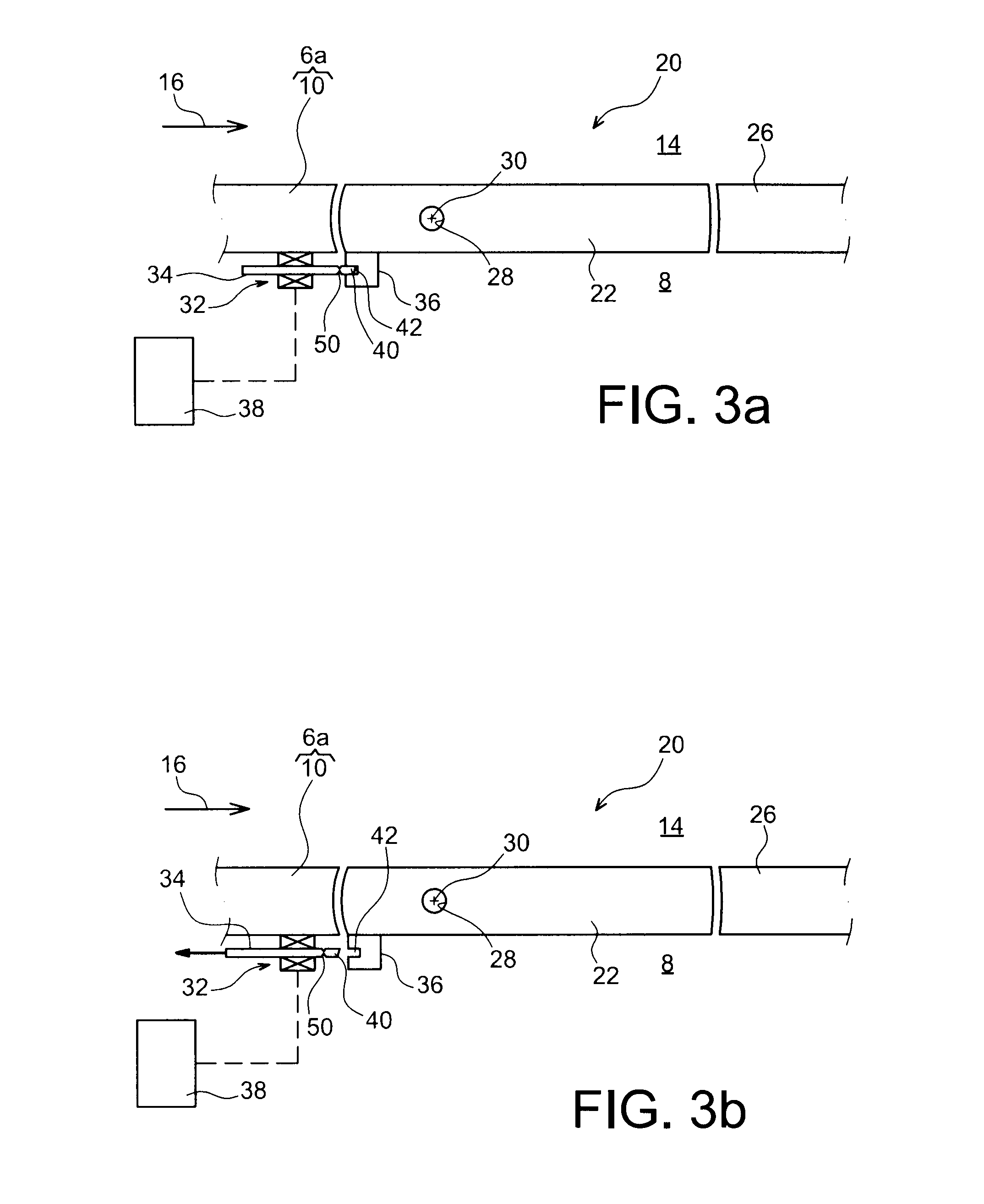
[0018]Preferably, this mobile output shaft integrates said mechanical fuse and has a beveled free end, both of these features may nevertheless be provided one without the other. The latter feature allows the opening leaf to be automatically locked upon its displacement from the open position to the closed position, without being hindered by the mobile output shaft capable of retracting temporarily under the effect of the force exerted by the opening leaf and / or the face plate of the locking means on the beveled end of the shaft, during the closing of the opening leaf.
[0020]Preferably, the nacelle element comprises an inner structure and an outer structure between which the secondary flow of the engine is intended to circulate, said door being laid out on said inner structure. As mentioned above, this gives the possibility of using the secondary flow of the jet turbine engine for exerting said closing gas pressure aiming at displacing the opening leaf from the open position to the closed position, without requiring any specific action on behalf of the operator.

Problems solved by technology

Further, when gases are found overpressurized with a level deemed unacceptable between the engine and the nacelle, for example following the bursting of a conduit, these gases may also be discharged through the same door.

Method used


Image

  • Dual function door for an aircraft engine nacelle
  • Dual function door for an aircraft engine nacelle
  • Dual function door for an aircraft engine nacelle

Examples


Embodiment Construction

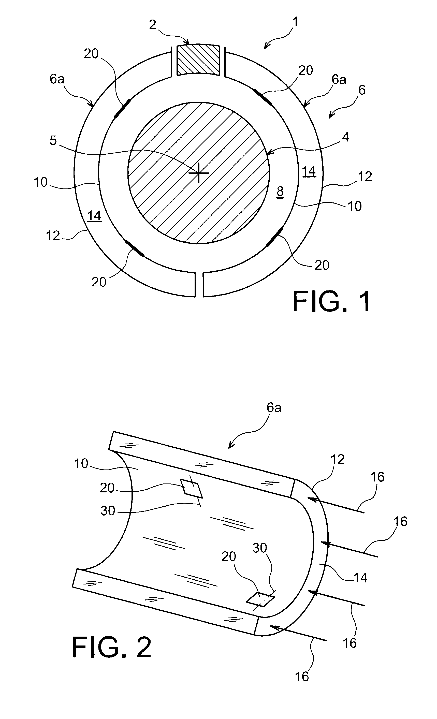
[0028]With reference to FIG. 1, an aircraft engine assembly 1 is seen, intended to be attached under a wing / aerofoil of this aircraft, this assembly 1 including an attachment pylon 2, a ducted-fan jet turbine engine 4, as well as a nacelle 6 surrounding the jet turbine engine 4 of longitudinal axis 5.

[0029]In FIG. 1, the engine assembly is illustrated in a sectional view passing through the engine compartment 8 located at right angles to the combustion chamber of the jet turbine engine, this engine compartment 8 being conventionally delimited axially between the fan and the case for ejecting the gases from the jet turbine engine, and radially between the nacelle 6 and the central case of the jet turbine engine. This compartment 8 is used for housing equipment / accessories of the engine.

[0030]In the illustrated sectional view, the nacelle 6 assumes the shape of two mobile nacelle cowls 6a, which are thrust inverter mobile cowls. Each of these cowls 6a assume the general shape of a hal...


PUM


Abstract

The invention relates to a door (20) for an aircraft engine nacelle (6), comprising an opening leaf (22), locking means (32, 36) with which the opening leaf may be locked in the closed position, as well as means (28) for setting the opening leaf (22) into motion with which the latter may be displaced from the closed position to the open position.According to the invention, said locking means have a mechanical fuse (50) intended to break under the effect of a force exerted by the opening leaf (22) and resulting from an opening gas pressure being applied on the opening leaf, with a value greater than or equal to a predetermined value and causing displacement of the opening leaf from the closed position to the open position after breakage of the mechanical fuse (50).

Description

TECHNICAL FIELD[0001]The present invention relates to a door for an aircraft engine nacelle, preferably intended to be implanted on a mobile cowl of the nacelle.[0002]The invention applies to nacelles which may house any types of engines, in particular ducted-fan jet turbine engines.STATE OF THE PRIOR ART[0003]In a known way, a nacelle surrounds an aircraft engine so as to form aerodynamic fairing around this engine. It comprises fixed elements and mobile elements, the latter being called nacelle cowls, and generally jointedly mounted on the pylon for attaching the engine.[0004]The nacelle interiorly defines a housing in which the engine provided with its equipment / accessories is laid out, the portion of this housing located at right angles to the combustion chamber being usually called the engine compartment. Upon stopping this engine, after a period of operation, hot air may accumulate in the space of the engine compartment left free between the nacelle and this same engine. In or...

Claims


Application Information

Patent Timeline
IPC IPC(8): B64D29/08B64C1/14B64D29/00E05F15/20
CPCB64D29/06F05D2240/14F01D25/24F01D21/00
Inventor GUILLAUME, PIERRELAIR, PATRICK
Owner AIRBUS OPERATIONS (SAS)
Learn More