Radiation tomography apparatus

a tomography and radiography technology, applied in tomography, optical radiation measurement, instruments, etc., can solve the problems of inability to employ configurations with maintenance difficulties, and achieve the effects of easy maintenance, poor detection sensitivity, and high sensitivity

Inactive Publication Date: 2011-12-08
SHIMADZU CORP
View PDF3 Cites 9 Cited by
  • Summary
  • Abstract
  • Description
  • Claims
  • Application Information

AI Technical Summary

Benefits of technology

[0010]The foregoing detector ring in the radiation tomography apparatus includes the first ring and the second ring. The first ring and the second ring are contained in the gantry. With such configuration, merely arranging housings may realize expansion of the field of view. According to this invention, two or more conventional detector rings are connected to manufacture radiation tomography apparatus having a large field of view.
[0011]Such configuration may provide radiation tomography apparatus with easier maintenance. For instance, when there arises a need to replace the first ring, the first housing is disconnected from the second housing. Consequently, the first ring contained in the first housing may be drawn out. With such specific configuration, the first housing is pulled out relative to the second housing in a direction perpendicular to a central axis, whereby the first ring is drawn out. The first ring is spaced away from the second ring, and a given clearance is provided between both the rings. Then, the first housing is pulled out under this state. Consequently, no interference of the first ring occurs with the second housing.
[0012]Moreover, both rings are connected through moving the first ring as to approach the second ring. Such configuration may provide radiation tomography apparatus with high sensitivity. If radiation tomography is conducted while a clearance is provided between both rings, some radiation emits from inside of the detector ring through the clearance. Such radiation does not enter into the radiation detector, and thus is not observed. Accordingly, the detector ring has poor detection sensitivity due to the clearance. On the other hand, according to this invention, the first ring moves as to approach the second ring, which results in a narrower clearance. Accordingly, radiation that is not observed may be reduced as much as possible.
[0013]Moreover, the gantry is held stationary when the foregoing first ring moves.
[0014]The above configuration represents a specific embodiment of the radiation tomography apparatus according to this invention. Specifically, the first ring moves relative to the gantry, whereby both the rings are connected. The gantry does not move to connect both the rings. In other words, in the radiation tomography apparatus, the first ring moves toward the second ring in the gantry. Accordingly, the first moving device for moving the first ring may be reduced in size.
[0017]Moreover, provided are a third ring having radiation detectors mentioned above annularly arranged, and a second moving device for moving the second ring relative to the second housing. The first ring, the second ring, and the third ring are spaced away in this order by a given clearance as to share each central axis. The first ring and the second ring synchronously move as to approach the third ring through control by the movement control device, whereby the three rings are connected. Such configuration is more desirable.

Problems solved by technology

However, the conventional radiation tomography apparatus has the following drawbacks.
Such configuration having difficulty in maintenance cannot be employed.

Method used


Image

  • Radiation tomography apparatus
  • Radiation tomography apparatus
  • Radiation tomography apparatus

Examples


embodiment 1

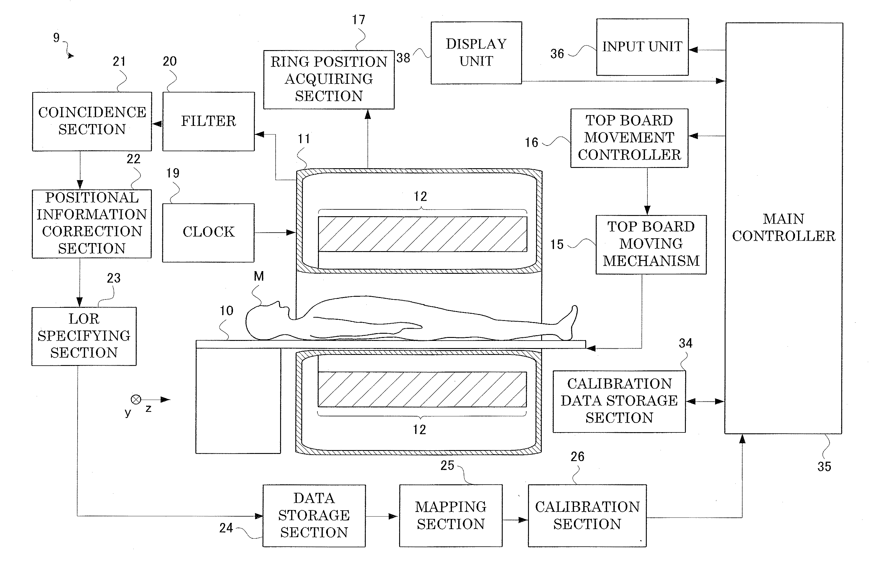
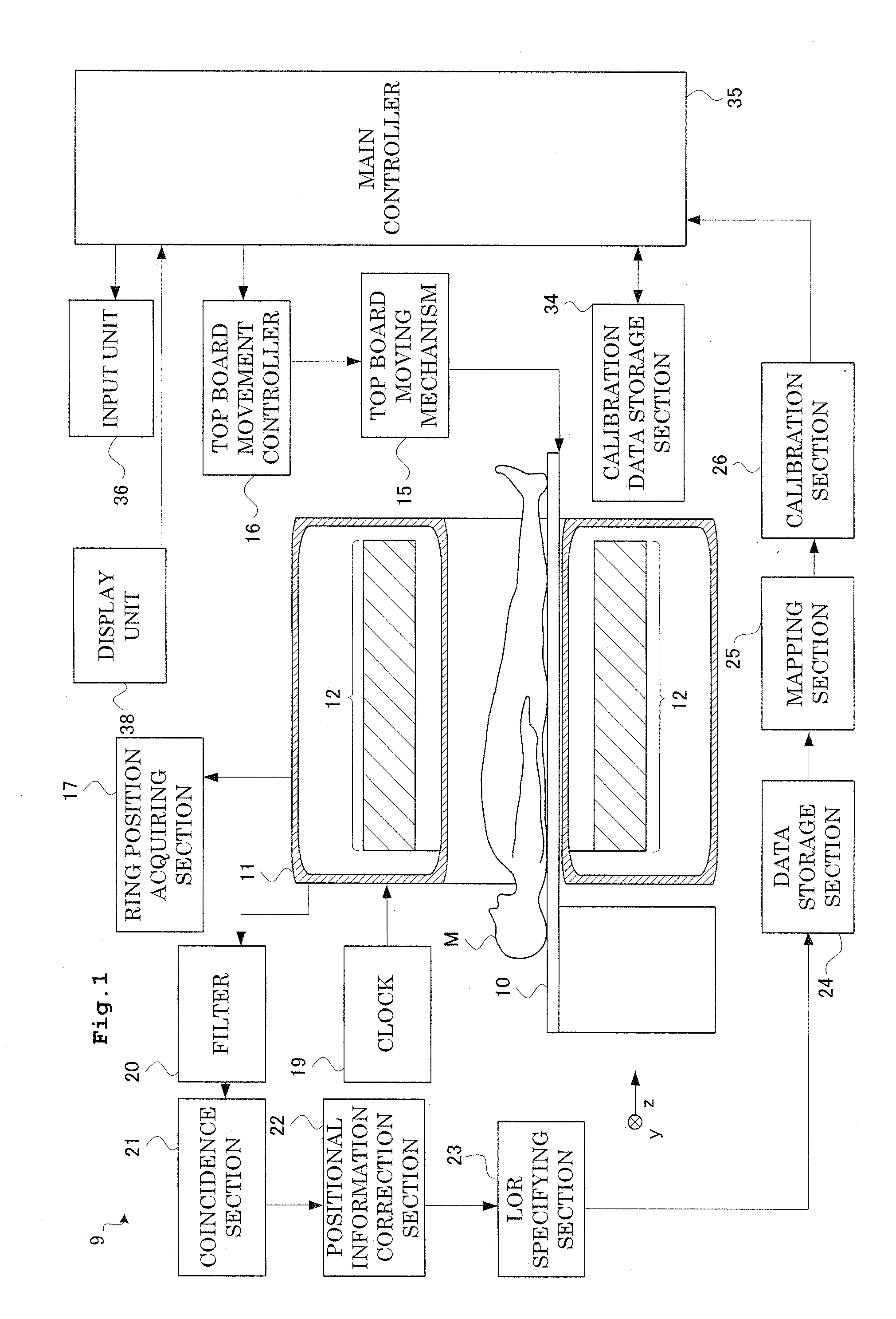
[0057]Each embodiment of radiation tomography apparatus according to this invention will be described hereinafter with reference to the drawings. FIG. 1 is a functional block diagram showing a configuration of radiation tomography apparatus according to Embodiment 1. As shown in FIG. 1, the radiation tomography apparatus 9 according to Embodiment 1 includes a top board 10 for placing a subject M on the back thereof, and a gantry 11 with a through hole for surrounding the subject M. The top board 10 is provided as to pass through an opening of the gantry 11. The top board 10 freely moves in and out along a direction where the opening of the gantry 11 extends. A top board moving mechanism 15 slides the top board 10 as above. A top board movement controller 16 controls the top board moving mechanism 15.

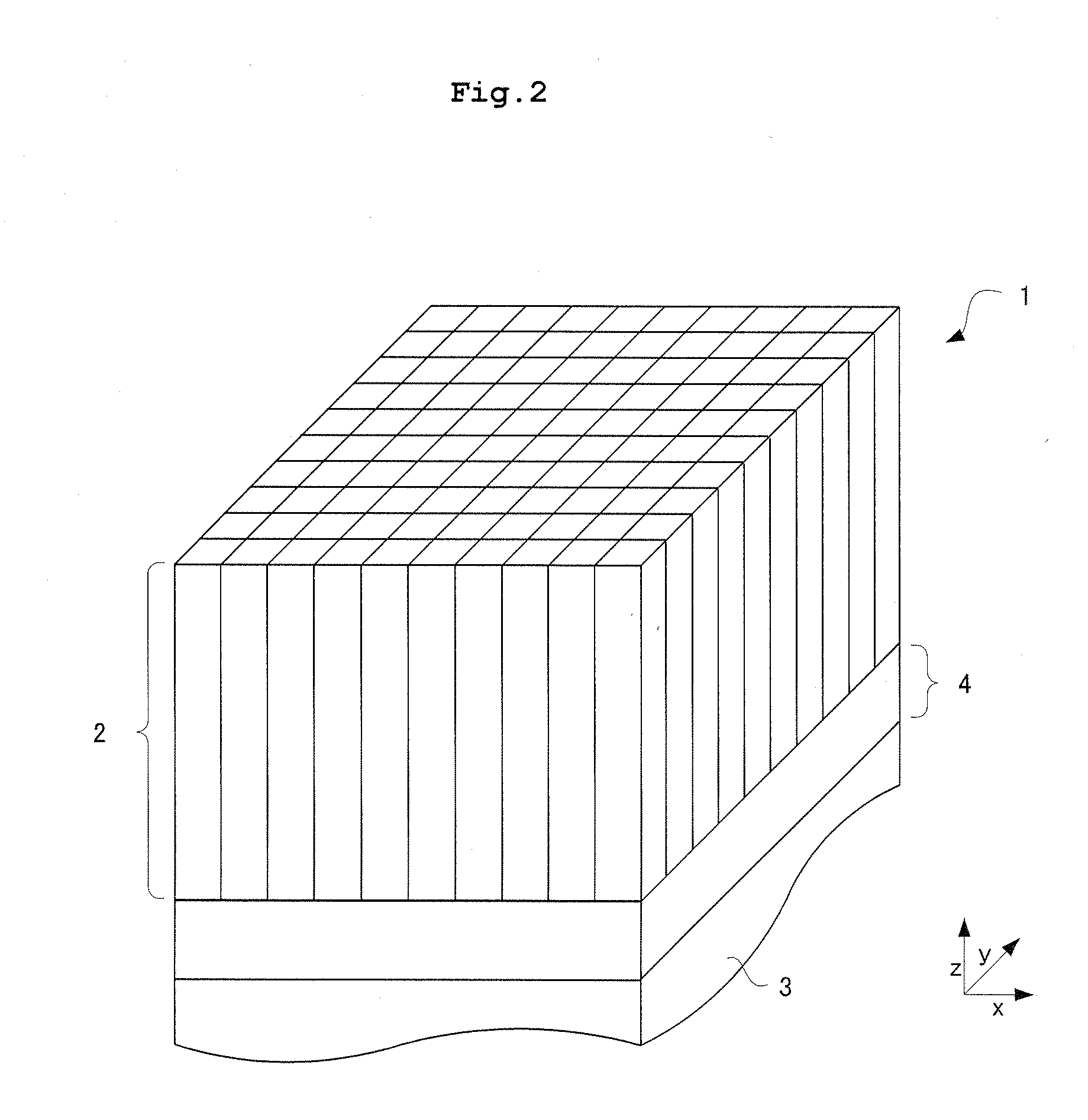
[0058]The gantry 11 includes a detector ring 12 inside thereof that detects annihilation gamma-ray pairs from the subject M. The detector ring 12 is tubular and extends in a body axis di...

embodiment 2

[0085]Next, description will be given of a PET / CT device according to Embodiment 2. The PET / CT device includes the radiation tomography apparatus (PET device) 9 described in Embodiment 1 and Embodiment 2, and a CT device for generating a sectional image using X-rays, and is medical apparatus that allows generation of a composite image having superimposed sectional images acquired in both devices.

[0086]Here, description will be given of a configuration of the PET / CT device according to Embodiment 2. The radiation tomography apparatus (PET device) 9 described in Embodiment 1 or Embodiment 2 may be used for the PET / CT device according to Embodiment 2. Consequently, description will be given of the CT device as a characteristic portion in Embodiment 2. As shown in FIG. 9, the CT device 8 has a gantry 45. The gantry 45 is provided with an opening that extends in the z-direction with a top board 10 inserted therein.

[0087]The gantry 45 has inside thereof an X-ray tube 43 for irradiating a ...


PUM


Abstract

One purpose of this invention is to provide radiation tomography apparatus with easier maintenance. A specific approach for this purpose is as follows. That is, a detector ring in the radiation tomography apparatus includes two or more rings. Moreover, a ring moves as to approach a next ring, whereby both the rings are connected. If radiation tomography is conducted while a clearance is provided between the rings, detection sensitivity of the detector ring decreases due to the clearance. On the other hand, according to this invention, the ring moves as to approach the next ring, which results in a narrower clearance. Accordingly, radiation that is not observed may be reduced as much as possible.

Description

TECHNICAL FIELD [0001]This invention relates to radiation tomography apparatus that images radiation emitted from a subject. Particularly, this invention relates to radiographic apparatus having a field that is wide enough to image a body portion of the subject at one time.BACKGROUND ART [0002]In medical fields, radiation emission computed tomography (ECT: Emission Computed Tomography) apparatus is used that detects an annihilation radiation (for example, gamma rays) pair emitted from radiopharmaceutical that is administered to a subject and is localized to a site of interest for acquiring sectional images of the site of interest in the subject showing radiopharmaceutical distributions. Typical ECT equipment includes, for example, a PET (Positron Emission Tomography) device and an SPECT (Single Photon Emission Computed Tomography) device.[0003]A PET device will be described by way of example. The PET device has a detector ring with block radiation detectors arranged in a ring shape....

Claims


Application Information

Patent Timeline
Patent Type & Authority Applications(United States)
IPC IPC(8): G01T1/16G01J1/42
CPCA61B6/032A61B6/037G01T1/2985A61B6/487G01T1/1611A61B6/4266
Inventor TANAKA, KAZUMIINOUE, YOSHIHIROAMANO, MASAHARUMIZUTA, TETSUROOHTANI, ATSUSHI
Owner SHIMADZU CORP
Why Eureka
Try Eureka