Supercharge Your Innovation With Domain-Expert AI Agents!

Electronic device with infrared touch input function

a technology of infrared touch and electronic devices, applied in the field of electronic devices, can solve the problem that the device is usually thicker than people, and achieve the effect of improving the accuracy of infrared touch input and reducing the risk of infrared touch interferen

Inactive Publication Date: 2011-12-08
HONG FU JIN PRECISION IND (SHENZHEN) CO LTD +1
View PDF12 Cites 5 Cited by
  • Summary
  • Abstract
  • Description
  • Claims
  • Application Information

AI Technical Summary

Benefits of technology

[0004]An infrared input system often includes a circuit board having a first pair of opposite sides positioned parallel to a first axis and a second pair of opposite sides positioned parallel to a second axis perpendicular to the first axis. The four sides corporately define a generally rectangular touch input area. A linear array of light emitting devices is arranged along each side. A light detection device is positioned at each corner of the circuit board. A controller is coupled to the light emitting devices and the light detection devices. The controller sequentially activates each linear array and activates the light detection devices positioned at the corners of the circuit board opposed to the activated array of light emitting devices. One problem with device using such an infrared input system is that the device is usually thicker than people otherwise expect.

Problems solved by technology

One problem with device using such an infrared input system is that the device is usually thicker than people otherwise expect.

Method used


Image

  • Electronic device with infrared touch input function
  • Electronic device with infrared touch input function
  • Electronic device with infrared touch input function

Examples


Embodiment Construction

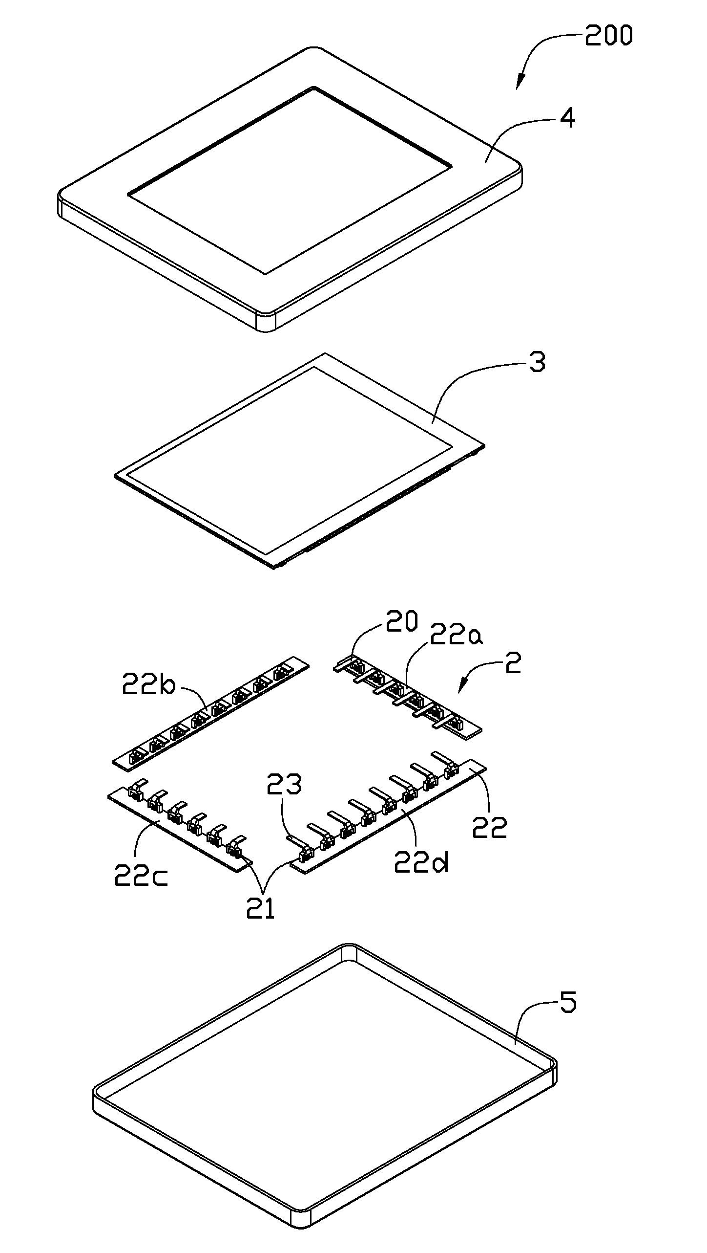
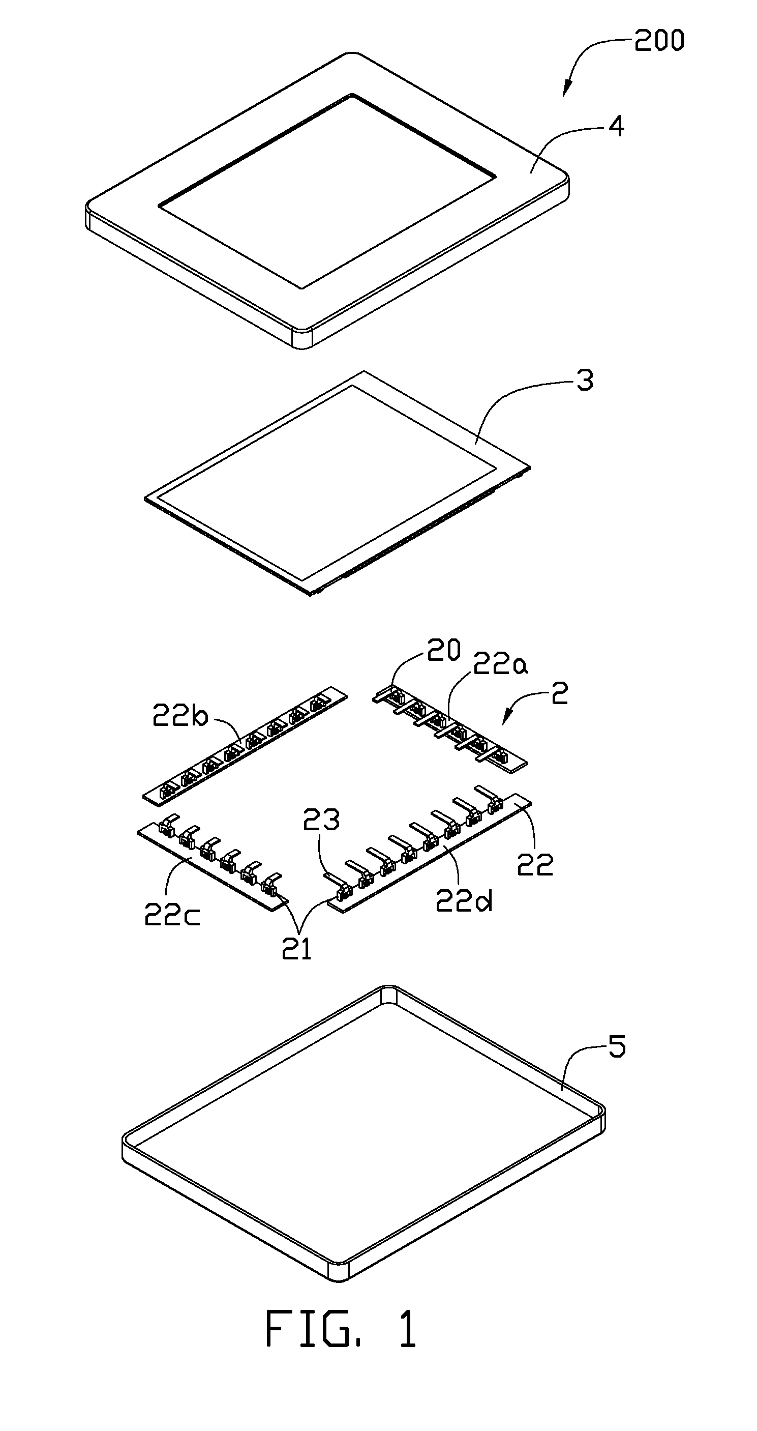
[0011]Referring to FIG. 1, an electronic device 200 with infrared touch input function includes an infrared touch module 2, a display panel 3, a front cover 4, and a rear cover 5. The display panel 3 may be a flat panel display defining an information display area. The infrared touch module 2 is mounted between the display panel 3 and the front cover 4. The infrared touch module 2 includes a linear array of infrared emitters 20, a linear array of infrared receivers 21, and a rectangular circuit board 22. In this embodiment, the circuit board 22 is divided into two pairs of oppositely disposed circuit boards 22a, 22b, 22c, and 22d, corporately defining an open area corresponding in size and shape corresponding to the information display area. The circuit boards 22a, 22b, 22c, 22d are arranged around the periphery of the display panel 3. The light emitters 20 are arranged along one side of each pair of adjacent circuit boards 22a, 22b, and the light receivers 21 are arranged along the...


PUM


Abstract

An electronic device includes a display panel and an infrared touch module. The infrared touch module includes a circuit board mounted parallelly under the display panel. An array of infrared emitters and receivers arranged along one side of each pair of adjacent sides of the circuit board, and facing a corresponding one of the array of light emitters on the opposite side. A light guide is mounted on each infrared emitter and each infrared receiver, and the light guide one each infrared emitter is operable to guide the light emitted from the light emitter to the corresponding infrared receiver via the light guide mounted thereon.

Description

BACKGROUND[0001]1. Technical Field[0002]The present disclosure relates to electronic devices, and particularly, to an electronic device with infrared touch input function.[0003]2. Description of the Related Art[0004]An infrared input system often includes a circuit board having a first pair of opposite sides positioned parallel to a first axis and a second pair of opposite sides positioned parallel to a second axis perpendicular to the first axis. The four sides corporately define a generally rectangular touch input area. A linear array of light emitting devices is arranged along each side. A light detection device is positioned at each corner of the circuit board. A controller is coupled to the light emitting devices and the light detection devices. The controller sequentially activates each linear array and activates the light detection devices positioned at the corners of the circuit board opposed to the activated array of light emitting devices. One problem with device using suc...

Claims


Application Information

Patent Timeline
IPC IPC(8): G06F3/042
CPCG06F3/0421
Inventor HSIEH, KUAN-HONGZHAO, XINHSIEH, KUN-CHIHLIN, WEN-HSINGPENG, BOLI, MING
Owner HONG FU JIN PRECISION IND (SHENZHEN) CO LTD
Features
  • R&D
  • Intellectual Property
  • Life Sciences
  • Materials
  • Tech Scout
  • Unparalleled Data Quality
  • Higher Quality Content
  • 60% Fewer Hallucinations
Learn More