Apparatus and method for controlling back light

a back light and control apparatus technology, applied in the field of back light control apparatus, can solve problems such as damage to devices, and achieve the effects of reducing and increasing the duty ratio of the pwm control signal

Inactive Publication Date: 2011-12-08
LG ELECTRONICS INC
View PDF5 Cites 28 Cited by
  • Summary
  • Abstract
  • Description
  • Claims
  • Application Information

AI Technical Summary

Benefits of technology

[0018]According to one aspect of another embodiment of the present invention, the step of setting a PWM control signal low to turn an LED backlight module off in a case a valid signal has not been inputted for a predetermined time is to stepwisely decrease a duty ratio of the PWM control signal to set it low.
[0019]According to one aspect of another embodiment of the present invention, the step of controlling the enable signal and the PWM control signal to turn the LED backlight module on in a case a valid signal is inputted after the LED backlight module turns off includes setting the enable signal high to output it to the LED backlight drive unit and increasing a duty ratio of the PWM control signal stepwisely after a predetermined time elapses from a point the enable signal is set high and thus output.
[0020]A backlight control method of another embodiment of the present invention may include controlling a PWM control signal and an enable signal to turn an LED backlight module off in a case a valid signal is not inputted for a predetermined time, setting the enable signal high and outputting it to an LED backlight drive unit in a case a valid signal is inputted after the LED backlight module turns off and increasing a duty ratio of the PWM control signal stepwisely after a predetermined time elapses from a point the enable signal is set high and thus output.

Problems solved by technology

Because a liquid crystal display panel is a light receiving device incapable of self-lighting, the liquid crystal display device requires the construction of a backlight unit supplying for separate lights.
Also, there is a problem that does damage to devices, for example transistors, because an over-current through an LED drive apparatus flows due to an abrupt current change.

Method used


Image

  • Apparatus and method for controlling back light
  • Apparatus and method for controlling back light
  • Apparatus and method for controlling back light

Examples


Embodiment Construction

[0024]A preferred embodiment according to the present invention will be described in consideration of the accompanying drawings. In the drawings, the same reference number refers to the same or like part.

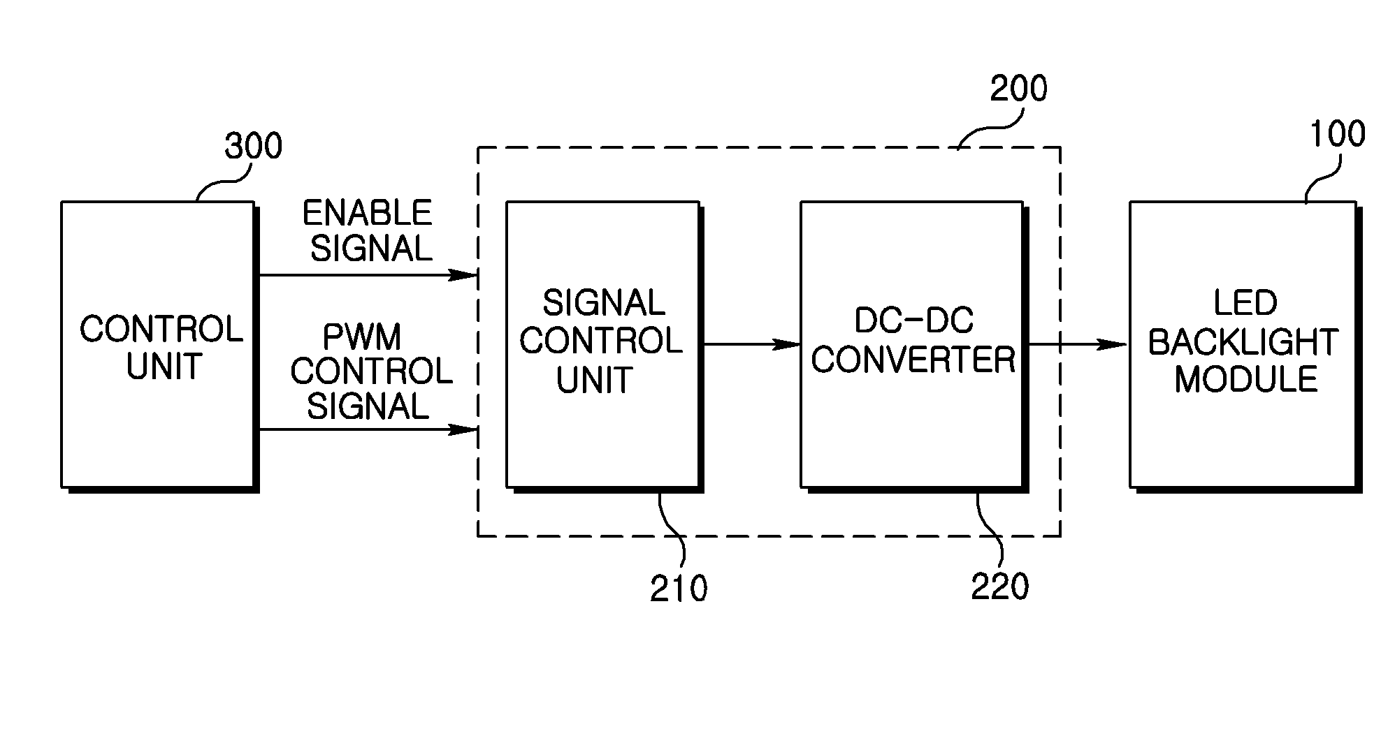
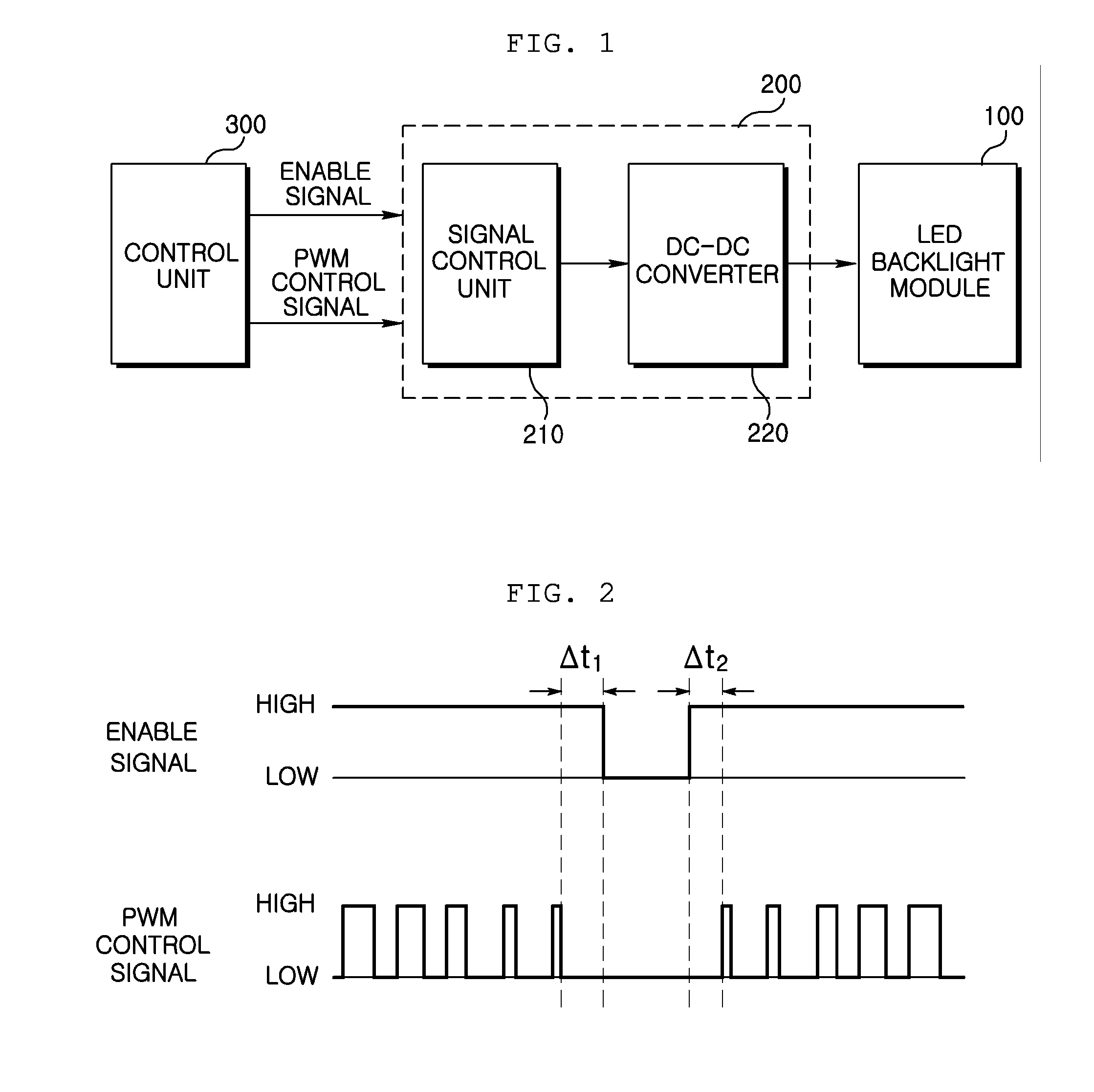
[0025]FIG. 1 is a block diagram showing the construction of a backlight control apparatus according to an exemplary embodiment of the present invention.

[0026]A backlight control apparatus according to one embodiment of the present invention can be applied to a LCD (Liquid Crystal Display) installed at a monitor, a TV, a laptop, etc., having an LED (Light Emitting Diode) backlight module as a light source employed in a LCD.

[0027]Referring to FIG. 1, a backlight control apparatus according to one embodiment of the invention includes an LED backlight module 100, an LED backlight drive unit 200, and a control unit 300.

[0028]An LED backlight module 100 includes a plurality of red (R) LEDs, green (G) LEDs and blue (B) LEDs radiating with luminance proportional to a supplied current. An LE...


PUM


Abstract

Disclosed herein is a backlight control apparatus, including an LED backlight drive unit driving an LED backlight module and a control unit outputting an enable signal deterministic of whether to drive the LED backlight drive unit or not to the LED backlight drive unit, and stepwisely decreasing or increasing the duty ratio of a PWM control signal to control the brightness of the LED backlight module and outputting it to the LED backlight drive unit.

Description

CROSS-REFERENCE TO RELATED APPLICATIONS[0001]Pursuant to 35 U.S.C. §119(a), this application claims the benefit of earlier filing date and right of priority to Korean Application No. 10-2010-0053513, filed on Jun. 7, 2010, the contents of which are hereby incorporated by reference herein in their entirety.BACKGROUND OF THE INVENTION[0002]1. Field of the Invention[0003]The present invention relates to a back light control apparatus controlling an enable signal and a PWM control signal inputted to an LED backlight drive unit in a case an LED backlight turns on, and a control method thereof.[0004]2. Description of the Related Art[0005]A liquid crystal display (LCD) device is one of flat panel display devices displaying images using liquid crystal. Because a liquid crystal display panel is a light receiving device incapable of self-lighting, the liquid crystal display device requires the construction of a backlight unit supplying for separate lights. The backlight unit may have a light ...

Claims


Application Information

Patent Timeline
Patent Type & Authority Applications(United States)
IPC IPC(8): G09G5/10
CPCG09G3/3406G09G2370/22G09G2330/022G09G2320/064G09G3/32G09G3/36G09G3/3611G09G2330/021
Inventor SHIN, JUNHO
Owner LG ELECTRONICS INC
Why Eureka
Try Eureka