Imaging apparatus

a technology of imaging apparatus and spherical tube, which is applied in the field of imaging apparatus, can solve the problems of increasing the size of the bottom wall portion, i.e., the housing member, and the inability to achieve a and achieves the effect of reducing the assemblability and achieving sufficient heat dissipation

Active Publication Date: 2011-12-08
RICOH KK
View PDF2 Cites 91 Cited by
  • Summary
  • Abstract
  • Description
  • Claims
  • Application Information

AI Technical Summary

Benefits of technology

[0015]An object of the present invention is to provide an imaging apparatus having a configuration in which an electronic circuit unit is fitted into a housing member through an opening in the housing member and by which a sufficient heat dissipation effect can be achieved without impeding downsizing thereof.

Problems solved by technology

Thus, a contact region allowing the contact with the soft heat transfer member is small, making it impossible to achieve a sufficient heat dissipation effect.
To expand the contact region, it may be conceivable to increase the area of the portion of the electronic circuit unit which faces the bottom wall portion of the housing member, but such increase causes a problem of increasing the size of the bottom wall portion, i.e., the housing member.
Thus, the assemblability may be lowered (deteriorated).
This makes it difficult to achieve desired contact states of the soft heat transfer members with the outer peripheral surfaces of the electronic circuit unit and desired contact states of the soft heat transfer members with the inner peripheral wall surfaces of the housing member.
Thus, there is a possibility that the heat dissipation effect may not be achieved as intended.

Method used


Image

  • Imaging apparatus
  • Imaging apparatus
  • Imaging apparatus

Examples


embodiment 1

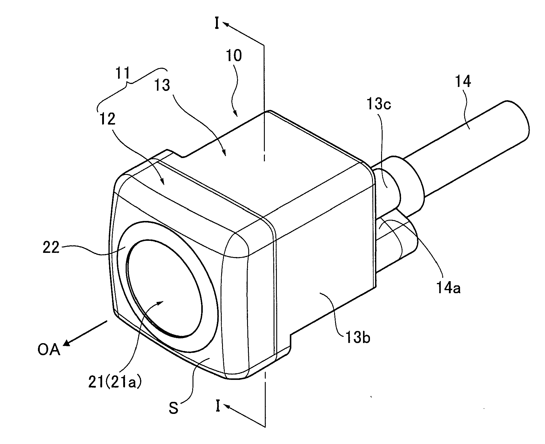
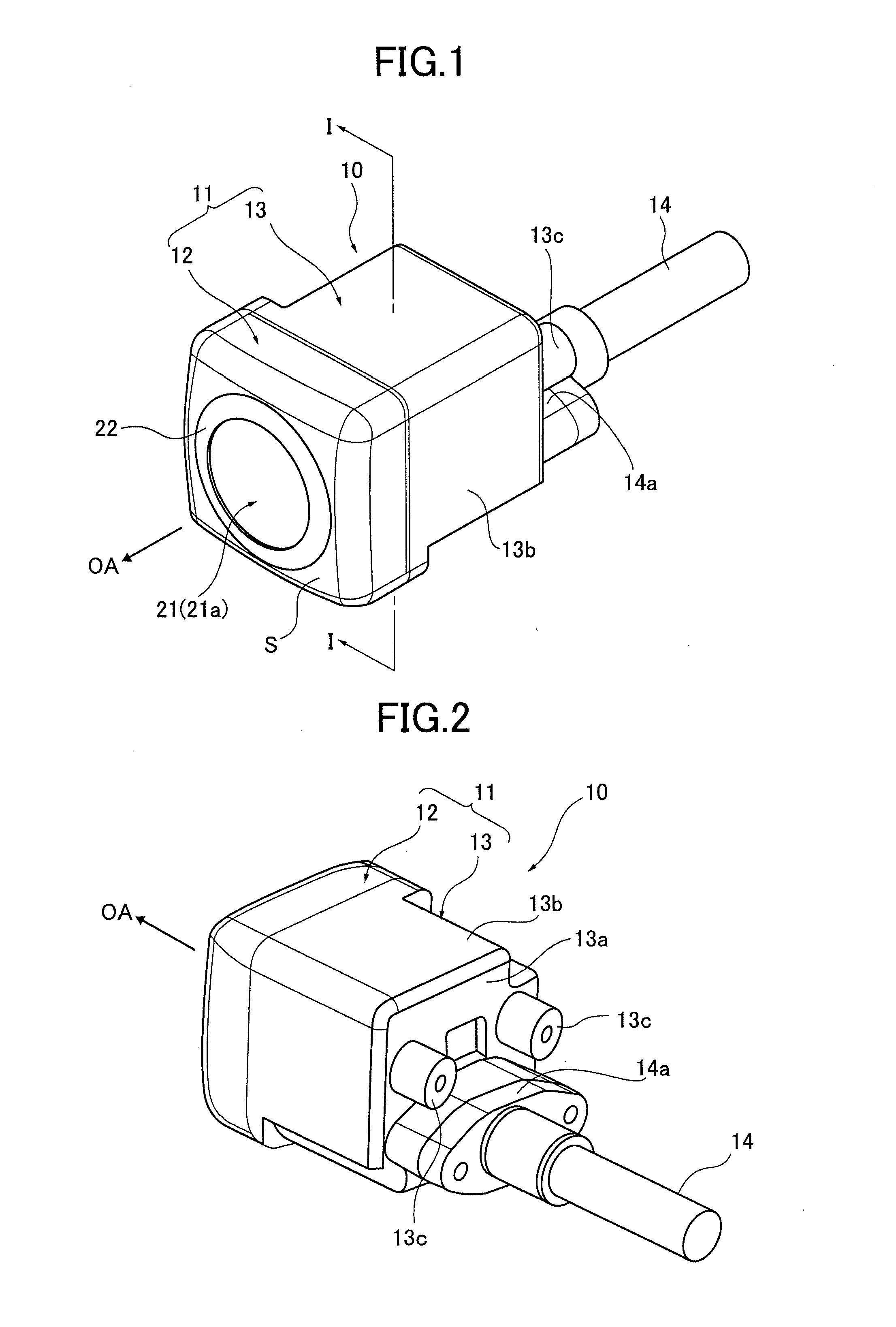
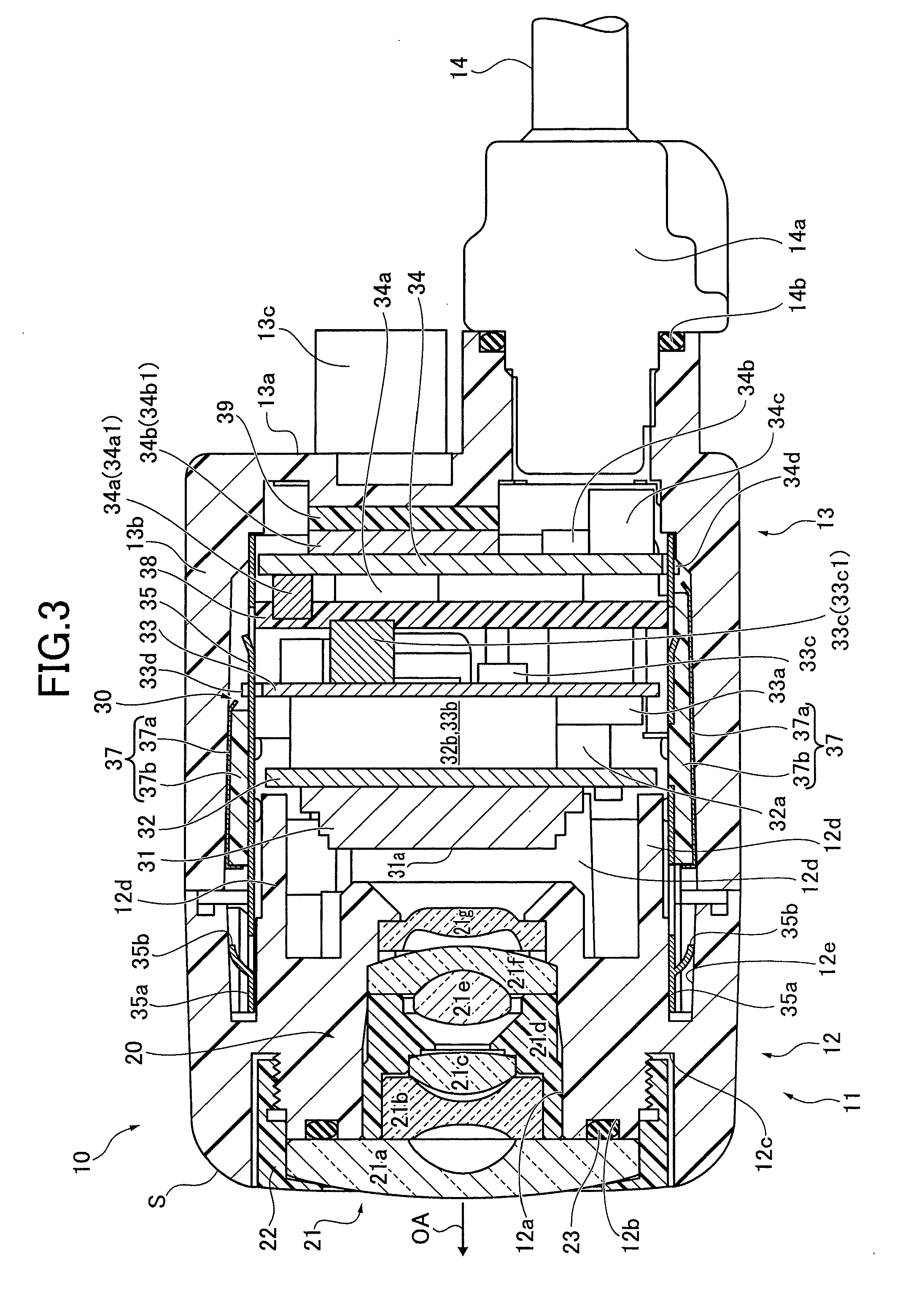
[0032]First, a schematic configuration of an imaging apparatus 10 of the present invention will be described referring to FIGS. 1 to 11. The imaging apparatus 10 is mainly formed of an imaging optical system 20 and an electronic circuit unit 30 which are housed inside a case 11. In the following, an object side of the imaging apparatus 10 in a direction along an imaging optical axis OA of the imaging optical system 20 is referred to as front (the direction indicated by the arrow OA), and the opposite side is referred to as rear.

[0033]In Embodiment 1, the case 11 includes: a front case part 12 supporting the imaging optical system 20; and a rear case part 13 housing the electronic circuit unit 30. The front case part 12 constitutes a front part of the case 11 (front case part) and forms an outer surface S surrounding a periphery of a lens system 21 of the imaging optical system 20 as viewed in a direction (hereinafter, also referred to as radial direction) perpendicular to the imagin...

embodiment 2

[0109]Next, an imaging apparatus of Embodiment 2 will be described as another example. An imaging apparatus in Embodiment 2 differs from the imaging apparatus 10 of Embodiment 1 due to the configuration of a first heat transfer member 372 provided to the outer peripheral surface of the electronic circuit unit 30. The basic configuration of the imaging apparatus of Embodiment 2 is the same as that of the imaging apparatus 10 of Embodiment 1. So, the common components are denoted by the same reference signs, and detailed description thereof is omitted. FIG. 12 is a schematic perspective view showing the first heat transfer member 372.

[0110]In the imaging apparatus of Embodiment 2, the first heat transfer member 372 (see FIG. 12) is provided to the outer peripheral surfaces of the electronic circuit unit 30. Like the first heat transfer members 37 of Embodiment 1, the first heat transfer member 372 joins the shield case 35 of the electronic circuit unit 30 and the peripheral wall porti...


PUM


Abstract

An imaging apparatus includes: an electronic circuit unit (30) including an imaging device (31) to acquire an object image formed by an imaging optical system (20); and a housing member (13) housing the electronic circuit unit (30). The electronic circuit unit (30) includes a thermally-conductive heat transfer member (37) in contact with an outer peripheral surface thereof which is in parallel with a fitting direction of the electronic circuit unit (30) into the housing member (13). The heat transfer member (37) includes a soft material portion (37b) in contact with the outer peripheral surface of the electronic circuit unit (37), and a plate portion (37a) in contact with the soft material portion (37b) and an inner peripheral wall surface of the housing member (13). The soft material portion (37b) is made of a shape-conformable member.

Description

[0001]CROSS-REFERENCE TO THE RELATED APPLICATIONS[0002]This application is based on and claims the priority benefit of Japanese Patent Application No. 2010-130358, filed on Jun. 7, 2010, the contents of which are incorporated herein by reference.BACKGROUND OF THE INVENTION[0003]1. Technical Field[0004]The present invention relates to an imaging apparatus used as a digital camera, digital video camera, and the like, and particularly to an imaging apparatus suitable for an in-vehicle camera and a surveillance camera.[0005]2. Background Art[0006]Heretofore, imaging apparatuses have been known which include an electronic circuit unit having an imaging device to acquire an object image formed by an imaging optical system including optical elements such as imaging lenses. A wide range of applications of such imaging apparatuses have been proposed such for example as an in-vehicle camera for supporting a driver's visual recognition from the inside of a vehicle, a surveillance camera instal...

Claims


Application Information

Patent Timeline
Patent Type & Authority Applications(United States)
IPC IPC(8): H04N5/225H04N7/18
CPCH04N5/2252H04N5/2251G03B17/55H04N23/52H04N23/51H04N23/55
Inventor INOUE, TOKIKOSASAKI, NORIHIKONAKAJIMA, MITSURU
Owner RICOH KK
Why Eureka
Try Eureka