LED lighting apparatus

a technology of led lighting and lighting apparatus, which is applied in the direction of discharge tube main electrodes, light and heating apparatus, semiconductor devices for light sources, etc., can solve the problems of prolonging the life of the led, unable to make full use of the feature of a low energy consumption of the led, and generating considerable heat, etc., to achieve sufficient heat dissipation effect, high heat dissipation effect, and quick diffusion

Active Publication Date: 2012-10-09
SWAN LITE MFG
View PDF6 Cites 0 Cited by
  • Summary
  • Abstract
  • Description
  • Claims
  • Application Information

AI Technical Summary

Benefits of technology

[0019]According to the first and second aspects, since the metallic heat conduction plate having the LED substrate unit mounted thereon is covered at both surfaces thereof with the resin heat radiation plates, the heat generated at the time of light emission of the LED can be quickly diffused by the heat conduction plate, and further, the diffused heat can be radiated via the heat radiation plates. The heat radiation plates are made of the resin having the high thermal emittance, thereby producing the sufficient heat dissipation effect accordingly. The heat dissipation effect is high in this manner, thus enhancing the durability of the LED.
[0020]In addition, since the heat conduction plate is covered at both surfaces thereof with the resin heat radiation plates having a low heat conductivity, there is no unpleasant feeling caused by the heat even if a person directly touches the apparatus.
[0021]Moreover, since the LED substrate unit is mounted on the heat conduction plate, the LED can be placed at an arbitrary position on the heat conduction plate without using a customized aluminum packaged substrate, thereby maintaining the characteristics as the lighting apparatus. As a result, no cost is added, unlike in the related art in which an electric circuit is designed on an aluminum plate according to the shape of a casing or the arrangement of an LED.
[0022]Additionally, the heat conduction plate and the heat radiation plates are made of plate members in the three-layered structure, making it possible to increase or decrease the entire thickness. In this manner, since the entire thickness can be freely determined, the freedom of design also is improved. In particular, each of the plates only needs to have the function of heat conduction or radiation, and therefore, the thickness of the plates can be reduced to an absolute minimum. For example, when the lighting apparatus is applied to a desk lamp, a totally new super thin type having an original design, which has not been observed in the related art, can be obtained.
[0023]When the thickness of the lighting apparatus is reduced to an absolute minimum, the weight thereof can be reduced. If the lighting apparatus having the reduced weight according to the present invention is applied to a desk lamp, a base part can be stably located even if it is made small. In this manner, the weight can be reduced, and further, the base part can be reduced in size, thereby enhancing packaging efficiency and transportation efficiency.
[0024]In addition, when the lighting apparatus is of a pendant type hanging from the ceiling, the weight reduction leads to the safety.

Problems solved by technology

However, when the LED substrate unit emits light, considerably high heat is generated.
As a result, it is impossible to make full use of the feature of a low energy consumption of the LED, and further, to prolong the lifetime of the LED.

Method used


Image

  • LED lighting apparatus
  • LED lighting apparatus
  • LED lighting apparatus

Examples


Embodiment Construction

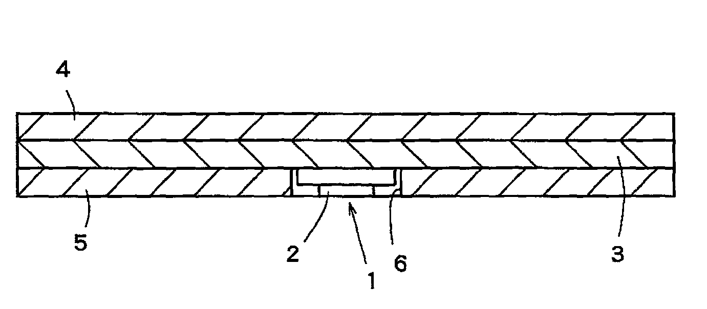
[0028]FIG. 1 is a cross-sectional view showing a lighting apparatus according to an embodiment of the present invention.

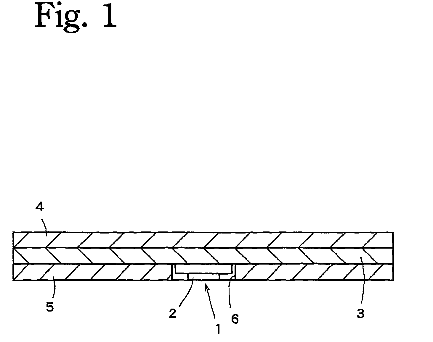
[0029]In the present embodiment, an LED substrate unit 1 is mounted on a heat conduction plate 3 made of aluminum, and heat radiation plates 4 and 5 made of an ABS resin (an acrylonitrile-butadiene-styrene copolymer) are respectively brought into close contact with entire both surfaces of the heat conduction plate 3 except a portion where the LED substrate unit 1 is attached. In this manner, the heat radiation plates 4 and 5 and the heat conduction plate 3 constitute a three-layered structure. Here, an opening 6 corresponding to the portion where the LED substrate unit 1 is attached is formed at the heat radiation plate 5 on the surface of the heat conduction plate 3 where the LED substrate unit 1 is attached.

[0030]Incidentally, the LED substrate unit 1 is a commercially available part obtained by unifying an LED chip 2 mounted on a substrate and the substrate.

[003...


PUM


Abstract

An object is to provide a lighting apparatus the cost of which is low, which is excellent in terms of heat dissipation capacity, and which does not make a human get burned even in the case where the human directly touches the lighting apparatus.An LED substrate unit (1) is mounted on a metal heat conduction plate (3) with high heat conductivity. Resin heat radiation plates (4, 5) with high thermal emittance and low heat conductivity are adhered to the entire exposure surface of both surfaces of the heat conduction plate (3) except for a portion on which the LED substrate unit (1) is mounted. Thus, a three layer structure is formed of the heat conduction plate and the heat radiation plates provided on both surfaces of the heat conduction plate. Heat discharged from the LED substrate unit (1) is diffused in the heat conduction plate (3) and transmitted to the resin heat radiation plates (4, 5), and the transmitted heat is discharged from the resin heat radiation plates (4, 5) to outer air.

Description

TECHNICAL FIELD[0001]The present invention relates to a lighting apparatus utilizing an LED as a light source.BACKGROUND ART[0002]There has been conventionally known the use of an LED substrate unit as energy-saving illumination which consumes less energy than other light sources.[0003]Moreover, the LED substrate unit has been highly expected as a light source for a thin lighting apparatus excellent in design since it is smaller in size than other light sources for an incandescent lamp or a fluorescent lamp.[0004]However, when the LED substrate unit emits light, considerably high heat is generated. If a temperature of an LED is increased due to the generated heat, conversion efficiency from electric energy into optical energy is degraded. As a result, it is impossible to make full use of the feature of a low energy consumption of the LED, and further, to prolong the lifetime of the LED.[0005]In order to solve the above-described problems, a lighting apparatus disclosed in Patent Doc...

Claims


Application Information

Patent Timeline
Patent Type & Authority Patents(United States)
IPC IPC(8): H01L33/00F21V29/00
CPCF21K9/00H05K1/0203F21V29/20H05K3/0064H05K2201/10106H05K1/053F21V29/503
Inventor KUROSAWA, HIDEYUKI
Owner SWAN LITE MFG
Why Eureka
Try Eureka